Replace NIC and HBA Cards
The 4U90 twin server chassis has four network interface (NIC) cards and two host bus adapter (HBA) cards. The cards are inserted from the top into keyed slots on the mother board and fastened with a retaining clip. Though the two types of cards are physically different, the removal and installation is the same.
Important Information
-
CRU kits that contain the HBA 9500 card (9-07806) require that the X200 system run ActiveScale Software 6.3 and above.
-
CRU kits that contain the HBA 9405 card (9-07552) do not have a minimum software requirement.
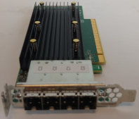
HBA Card
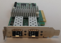
NIC Card
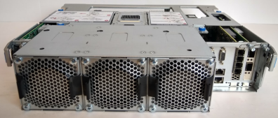
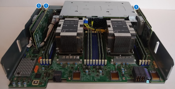
Compute Node Modules in 4U90 Twin Server Chassis
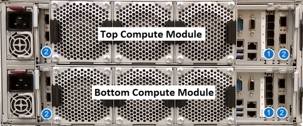
| Item | Name |
|---|---|
| 1 | HBA Cards |
| 2 | NIC Cards |
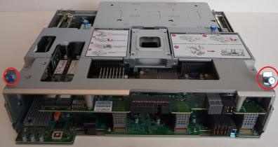
Remove NIC or HBA Card
-
Hold down the power button of the compute module to be removed for at least 4 seconds.
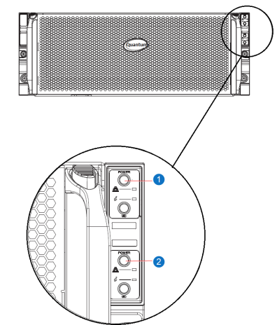
| Item | Name |
|---|---|
| 1 | Top Compute Node Power Button |
| 2 | Bottom Compute Node Power Button |
-
Disconnect all power supply cords and all network and system cables from the compute module.
Note: Before disconnecting cables, document the cable configuration. The cabling must be reconnected to the module in the exact same configuration.
-
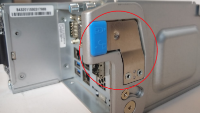
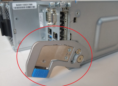
Unlock the left and right latches on the side of the compute module.
-
Remove the compute module from the chassis and place on a flat surface.
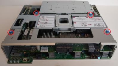
To access the card slots in the compute module, you will need to remove the mezzanine (node) module from the compute module.
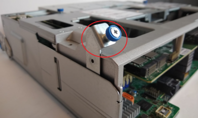
-
Unscrew the four screw thumbs on top of the module.
-
Lift the left and right latches to the unlock position.
-
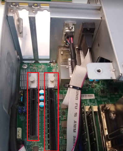
Vertically lift the module out of the chassis. You will now have access to the card slots in the compute module.
Item Name 1 Card Slots
WARNING: Use care when removing the cards. They are very close to each other and there is a rick of damaging components on the card
-
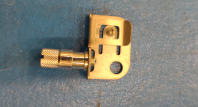
Loosen the captive screw where the top of the card meets the chassis.
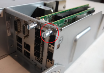
-
Pull the clip away from the chassis and card.
-
Carefully remove the card by pulling it up and away from the motherboard.
Replace NIC or HBA Card
WARNING: Use care when replacing the cards. They are very close to each other and there is a rick of damaging components on the card
-
Install the card by carefully pushing it down until it is completely seated into the appropriate keyed slot in the motherboard.
-
Insert the clip to connect the chassis to the card.
-
Tighten the captive screw where the top of the card meets the chassis.
-
Make sure the left and right latches are in the unlocked position. Align the mezzanine module vertically and lower into the compute module.
-
Rotate the left and right latches forward to the lock positions.
-
Carefully push down the middle section of the module to ensure connectors are fully engaged.
-
Fasten the 4 blue thumb screws on top of the module.
-
Carefully slide the compute module back into the chassis.
-
Lock the left and right latches on the side of the compute module.
-
Reconnect the power cable to the power supply and all network and system cables to the compute node.
-
Press the node power button once. The compute node control board will initiate the power up sequence.
-
Wait a few minutes for the node to power up and spin up all disks.
| Item | Name |
|---|---|
| 1 | Top Compute Node Power Button |
| 2 | Bottom Compute Node Power Button |