|
|
Xcellis Workflow Director Rack Configurations |

The following applies to Xcellis Workflow Director and aiWARE for Xcellis Embedded (DAE) systems.
The order in which you will rack your system depends on the server and QXS chassis components that you have purchased. The following diagrams display the types of components that you can install into the different rack zones, and potential rack configurations.
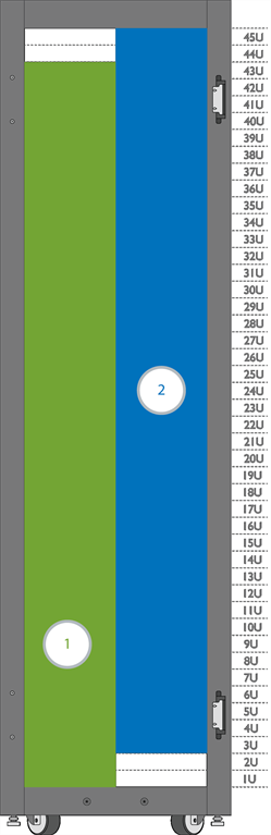
The following diagram displays the types of components that can be installed into each of the rack zones. Rack zones indicate the related components that must be grouped together within the rack. Keep in mind that you can generally apply the rack zones, regardless of the number of optional components in your particular configuration.
|
Zone |
Color |
|---|---|
|
Zone 1 – Range for QXS RAID and expansion chassis |
|
|
Zone 2 – Range for server nodes |
|
|
We recommend installing rack-mounted hardware, such as Fibre Channel / iSCSI switches, network switches, and additional power outlets, at the top of the rack. |
|
The following examples are representative of different rack configurations by zone. Keep in mind that these examples are not exhaustive. Additional rack space may be needed for certain hardware configurations, such as configurations with multiple QXS systems that include a RAID chassis and one or more expansion chassis.
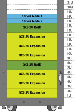
The following diagram shows a dual-node system with 6 x 2U expansion chassis.
- 3 expansion chassis are connected to the upper 2U QXS RAID chassis
- 3 expansion chassis are connected to the lower 2U QXS RAID chassis via SAS connections.
- Both RAID chassis are connected to the server node via an appropriate Fibre Channel switch.
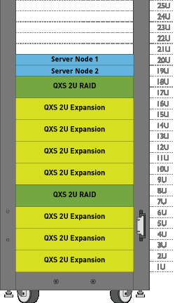
The following diagram shows a dual-server node system with 7 x 2U expansion chassis, as an example of a mixed quantity of expansion modules attached to two separate QXS RAID chassis.
- 4 expansion chassis are connected to the upper 2U QXS RAID chassis
- 3 expansion chassis are connected to the lower 2U QXS RAID chassis via SAS connections.
- Both RAID chassis are connected to the server node via an appropriate Fibre Channel switch.
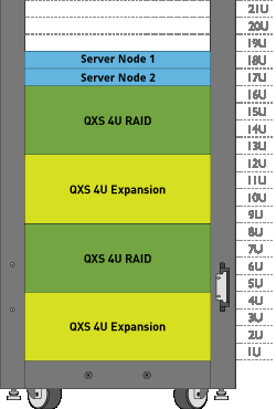
The following diagram shows a dual-server node system with 2 expansion chassis.
- 1 expansion chassis is connected to the upper RAID chassis
- 1 expansion chassis is connected to the lower RAID chassis via SAS connections.
- Both RAID chassis are connected to the server node via an appropriate Fibre Channel switch.
*Back to Hardware Installation Overview and Checklist *