Server Rack – Remove and Replace
WARNING: Because of the chassis weight, two people are required to lift it.
- If not done previously, remove all power, Ethernet, and Fibre Channel cables from the back of the server.
- Hold the power button in at least 20 seconds to discharge all of the condensers before opening the server.
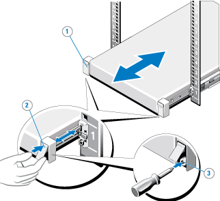
- If used, remove the screws under each latch with a #2 PHILLIPS® screwdriver (3) which secure the server to the front of the rack.
- Facing the front, locate the slam latch on either side of the server (1).
- The latches engage automatically as the system is pushed into the rack and are released by pulling up on the latches (2).
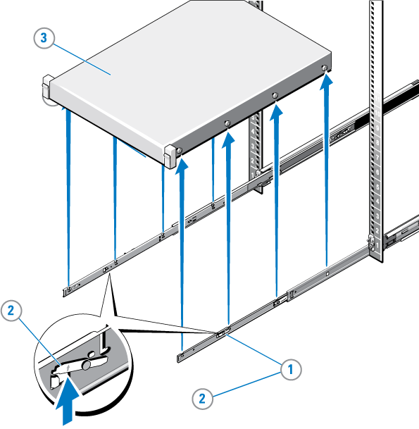
- Locate the lock levers on the sides of the inner rails (1).
- Unlock each lever by rotating it up to its release position (2).
- Grasp the sides of the server firmly and pull it forward until the rail standoffs are at the front of the J-slots. Lift the server up and away from the rack and place it on a level surface (3).
Note: If not done previously, label the cables so they can be easily identified when they are connected back to the server after the replacement procedure.
Figure 1: Unlocking the Server Node Rail Latches
WARNING: Because of the chassis weight, two people are required to lift it.
Figure 2: Pulling the Server Node From the Rack
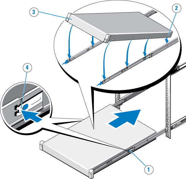
- Place the MDC Node into the rail J-slots.
- Push the rail levers in on both sides of the server, and slide the server into the rack until it clicks into place.
- If needed, install a hard-mount screw under each latch with a #2 PHILLIPS® screwdriver to secure the server Node to the front of the rack.
- Unless this will be done later, connect Ethernet, Fibre Channel and power cables to the back of the server Node. Use the labels applied earlier to identify where these cables should be connected.
WARNING: Because of the chassis weight, two people are required to lift it.
Figure 3: Installing the Server in a Rack