Replace DIMM Memory
CRU Part Number: 9-07538
Overview
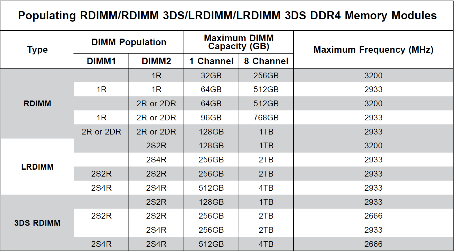
The server contains DIMM memory modules and supports up to 4 TB registered ECC DDR4 3200MHz RDIMM/LRDIMM/3DS/NVDIMM in 16 DIMM slots. Refer to the table below for additional memory information.
Caution: Exercise extreme caution when installing or removing memory modules to prevent damage to the DIMMs or slots.
There is no specific order or sequence required when installing memory modules; however, Quantum recommends you keep the following in mind:
-
Always use DDR4 DIMM modules of the same type, size and speed.
-
Mixed DIMM speeds can be installed, however, all will run at the speed of the slowest DIMM.
-
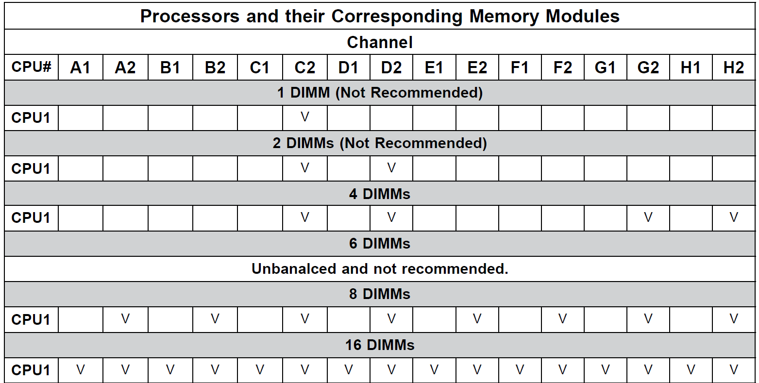
The motherboard will support odd-numbered modules (1 or 3 modules installed); however, to achieve the best memory performance, Quantum recommends a balanced memory population.
-
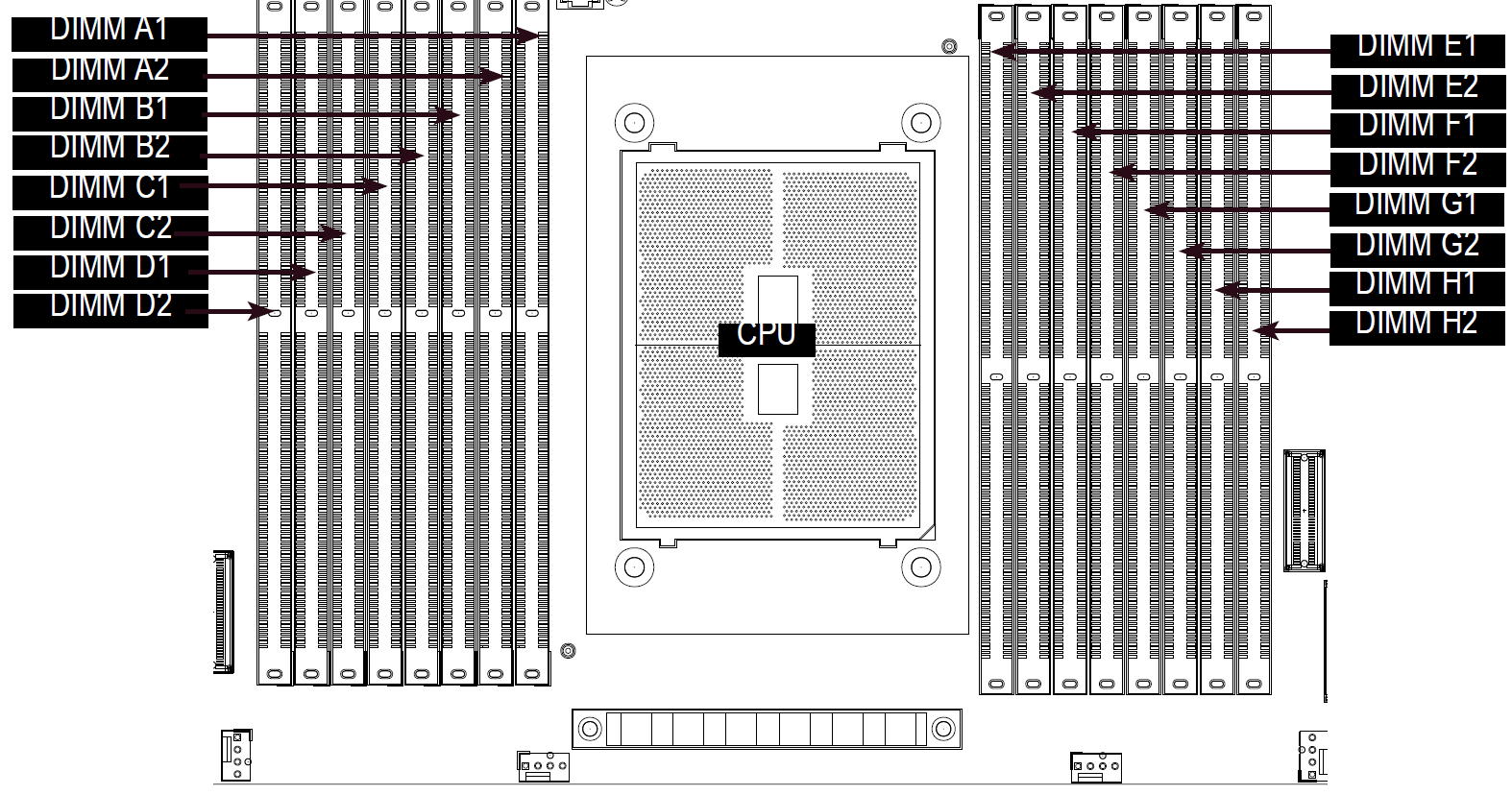
To achieve optimal memory performance, the minimum recommended is at least one DIMM for each channel pair in the system (for example, A, C, E, G).
Caution: The memory modules must be replaced in the same slots on the motherboard.
Replacement Procedure
Required Tools: There are no tools required for this component replacement.
Take ESD precautions when performing this replacement
The chassis is designed to dissipate all electrostatic discharge (ESD) to the chassis base. Ensure that there is sufficient electrical and mechanical connection from the chassis base to the rack rails, and that the rack itself is tied to earth ground. The unit must be grounded in accordance with all local/regional and national electrical codes.
Some components within the node contain static-sensitive parts. Precautions must be taken to ensure that the system is not exposed to ESD while handling components or servicing the unit. To avoid damaging these parts while performing maintenance procedures, always observe the following precautions:
-
Keep static-sensitive parts in their original shipping containers until ready for installation.
-
Do not place static-sensitive parts on a metal surface. Place them inside their protective shipping bag or on an anti-static mat.
-
Wear anti-static wrist bands when unpacking and handling the units, and avoid touching connectors and other components.
-
Dry climates and cold-weather heating environments have lower relative humidity and are more likely to produce static electricity.
-
Remove power from the server.
-
Hold down the power button for at least 4 seconds.
Note: The power button applies or removes primary power from the power supply to the node but maintains standby power. Once the node has powered down, unplug the power cords to the node power supplies to remove all power.
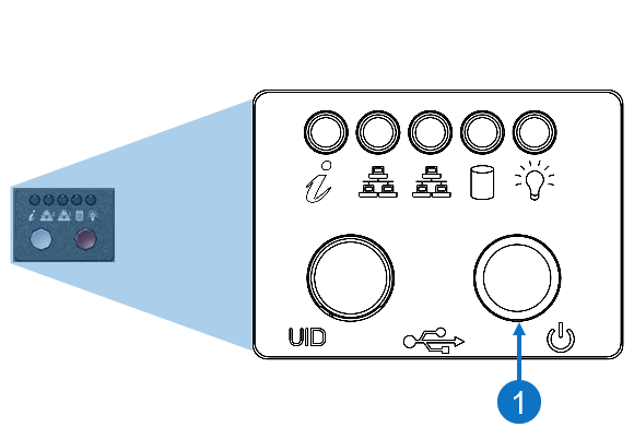
Item Description 1 Power Button
-
-
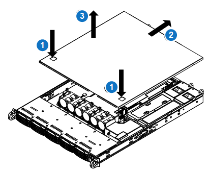
Remove the chassis cover to access the modules on the motherboard.
-
Grasp the two handles on either side and pull the unit straight out until it locks (you will hear a "click").
-
Depress the two buttons on the top of the chassis to release the top cover and at the same time, push the cover away from you until it stops.
-
Lift the top cover from the chassis to gain full access to the inside of the server.
-
-
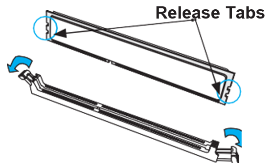
Press the release tabs on both ends of the DIMM socket to release the DIMM module from the socket as shown in the drawing below.
-
Push the release tabs outwards on both ends of the DIMM slot to unlock it.
-
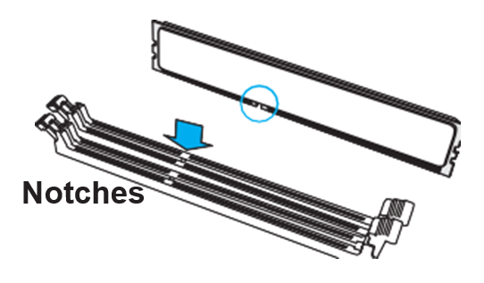
Align the key of the new DIMM with the receptive point on the memory slot.
-
Align both ends of the module with the receptive points on the ends of the slot.
-
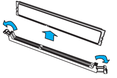
Use two thumbs together to press the DIMM straight down into the slot until it snaps into place.
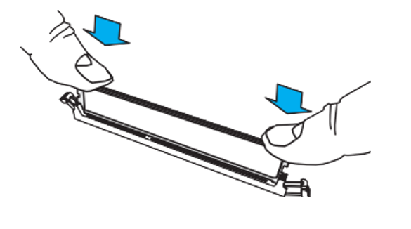
-
Press the release tabs to the lock positions to secure the DIMM into the slot.
-
Install the chassis cover.
-
Power up the system.
-
Plug the power cords into the rear of the power supplies.
-
Press the power button once. The server control board will initiate the power up sequence.
Item Description 1 Power Button
-