Replace Fans
CRU Part Number: 9-07556
Overview
The server contains six 4 cm counter-rotating fans provide cooling for the system.
Fan LEDs
The Universal Information LED on the server control panel will indicate a fan failure has occurred.
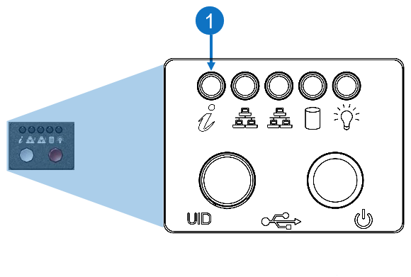
| Item | LED/Button | Description |
|---|---|---|
| 1 | Universal Information |
|
Check the Server Air Flow
-
Make sure there are no objects to obstruct airflow in and out of the server.
-
Do not operate the server without drives or drive trays in the drive bays.
-
Use only recommended server parts.
-
Make sure no wires or foreign objects obstruct air flow through the chassis. Pull all excess cabling out of the airflow path or use shorter cables.
Overheating
The control panel LEDs display system heat status.
There are several possible responses if the system overheats. If the server overheats:
-
Use the LEDs to determine the nature of the overheating condition.
-
Confirm that the chassis covers are installed properly.
-
Make sure all fans are present and operating normally.
-
Check the routing of the cables.
-
Verify that the heat sinks are installed properly.
Replacement Procedure
Required Tools: There are no tools required for this component replacement.
Take ESD precautions when performing this replacement
The chassis is designed to dissipate all electrostatic discharge (ESD) to the chassis base. Ensure that there is sufficient electrical and mechanical connection from the chassis base to the rack rails, and that the rack itself is tied to earth ground. The unit must be grounded in accordance with all local/regional and national electrical codes.
Some components within the node contain static-sensitive parts. Precautions must be taken to ensure that the system is not exposed to ESD while handling components or servicing the unit. To avoid damaging these parts while performing maintenance procedures, always observe the following precautions:
-
Keep static-sensitive parts in their original shipping containers until ready for installation.
-
Do not place static-sensitive parts on a metal surface. Place them inside their protective shipping bag or on an anti-static mat.
-
Wear anti-static wrist bands when unpacking and handling the units, and avoid touching connectors and other components.
-
Dry climates and cold-weather heating environments have lower relative humidity and are more likely to produce static electricity.
-
If necessary, remove the chassis cover while the system is running to locate the position of the failed fan. Do not run the server for an extended time with the cover off.

-
Log in to the BMC and execute a power off command to perform a clean power down of the system. Alternatively, execute the poweroff command using the CLI.
-
Remove the chassis cover to access the fans.
-
Grasp the two handles on either side and pull the unit straight out until it locks (you will hear a "click").
-
Depress the two buttons on the top of the chassis to release the top cover and at the same time, push the cover away from you until it stops.
-
Lift the top cover from the chassis to gain full access to the inside of the server.
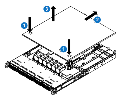
Caution: Except for short periods of time, do not operate the system without the cover in place. The chassis cover must be in place to allow proper airflow and to prevent overheating.
-
-
Unplug the fan cable from the motherboard and remove the failed fan from the chassis.
-
Lift the failed fan from the fan housing and out of the chassis.
-
Push the new fan into the vacant space in the housing while making sure the arrows on the top of the fan (indicating air direction) point in the same direction as the arrows on the other fans.
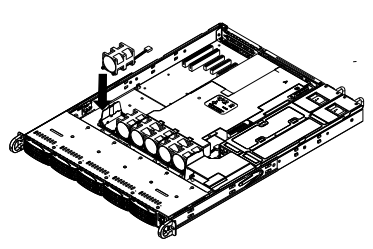
-
Reposition the fan housing back over the two mounting posts in the system, then reconnect the fan wires to the same fan headers on the motherboard.
-
Power up the system and check that the fan is working properly before reinstalling the chassis cover.
-
Plug the power cords into the rear of the power supplies.
-
Press the power button once. The server control board will initiate the power up sequence.
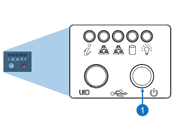
Item Description 1 Power Button
-
-
Reinstall the chassis cover.