Hardware Overview
The Xcellis Workflow Extender (Gen 2) system is a single server gateway appliance that supports various configurations and options to provide access to the StorNext SAN from SAN and/or NAS clients.
Figure 1: Front View - (with bezel)

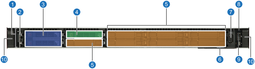
Figure 2: Front View (without bezel; with a PERC RAID card; hardware RAID)

Figure 3: Front View (without bezel; no PERC RAID card; software RAID)
![]()
The front panel of the server node includes the following features and indicators.
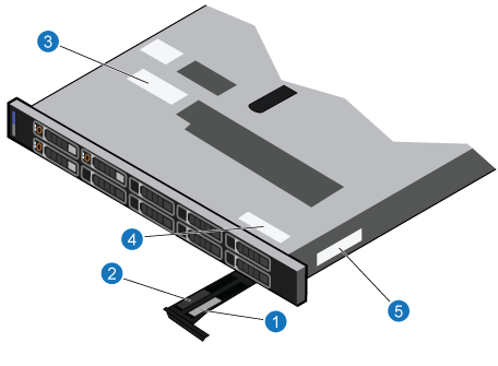
Figure 4: Front panel – Xcellis Workflow Extender (with a hardware RAID/PERC RAID card).
|
Item |
Indicator, button, or connector |
Icon |
Description |
|---|---|---|---|
|
1 |
n/a |
Contains the status LED indicators. The status LEDs enable you to identify any failed hardware components. There are up to five status LEDs and an overall system health LED (Chassis health and system ID) bar. |
|
|
2
|
n/a |
Indicates the system health. |
|
| 3 | System drives | n/a | These two 2.5 inch hot-swappable SSDs contain the server Operating System, StorNext software, appliance code and all server features. |
| 4 | Scratch drive | n/a | This single 1 TB 2.5 inch hard drive is used by the server for scratch disk storage (temporary information used for firmware upgrades, StorNext Connect data, etc.). |
|
5 |
7 additional drive bays |
n/a |
These drive bays are filled with drive blanks; they do not contain drives. |
|
6 |
Service tag |
n/a |
This large pull-out tab contains the server Service Tag, and the StorNext System Serial Number. |
|
7 |
Video connector |
|
Used to connect a VGA display to the server. |
|
8 |
Power button |
|
Indicates if the server is turned on or off. Press the power button to manually turn the server on or off. Note: When you turn off the server with the Power button, the server performs the equivalent of a Linux "-poweroff" (graceful shutdown) before powering off. For normal server operations, use the appropriate system Power Off procedure. |
|
9 |
USB port |
|
This is a 4-pin, USB 2.0-compliant port, and enables you to connect USB devices to the system. |
|
10 |
Server release buttons |
n/a |
Use these buttons together to release the server from the rack, and pull the server out on its rails. |


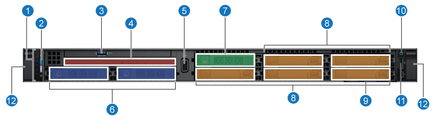
Figure 5: Front panel – Xcellis Workflow Extender (with a software RAID/without PERC RAID card).
|
|
Indicator, button, or connector |
Icon |
Description |
|---|---|---|---|
|
1 |
n/a |
Contains the status LED indicators. The status LEDs enable you to identify any failed hardware components. There are up to five status LEDs and an overall system health LED (Chassis health and system ID) bar. |
|
|
2
|
n/a |
Indicates the system health. |
|
| 3 | USB port | n/a | This is a 4-pin, USB 2.0-compliant port, and enables you to connect USB devices to the system |
| 4 | DVD drive | n/a | Optical drive. |
|
5 |
Video connector |
|
Used to connect a VGA display to the server. |
| 6 | System boot drives | n/a | These two 2.5 inch hot-swappable SSDs contain the server Operating System, StorNext software, appliance code and all server features. |
| 7 | Scratch drive | n/a | This single 1 TB 2.5 inch hard drive is used by the server for scratch disk storage (temporary information used for firmware upgrades, StorNext Connect data, etc.). |
|
8 |
5 additional drive bays |
n/a |
These drive bays are filled with drive blanks; they do not contain drives. |
|
9 |
Service tag |
n/a |
This large pull-out tab contains the server Service Tag, and the StorNext System Serial Number. |
|
10 |
Power button |
|
Indicates if the server is turned on or off. Press the power button to manually turn the server on or off. Note: When you turn off the server with the Power button, the server performs the equivalent of a Linux "-poweroff" (graceful shutdown) before powering off. For normal server operations, use the appropriate system Power Off procedure. |
|
11 |
USB port |
|
This is a 4-pin, USB 2.0-compliant port, and enables you to connect USB devices to the system. |
|
12 |
Server release buttons |
n/a |
Use these buttons together to release the server from the rack, and pull the server out on its rails. |
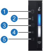
Note: The status LED indicators are always off and only turns on to a solid amber if any error occurs.
|
Number |
Icon |
Description |
Condition |
|---|---|---|---|
| 1 |
|
Drive indicator |
The indicator turns solid amber if there is a drive error. • Check the System Event Log to determine if the drive has an error. |
| 2 |
|
Temperature indicator |
The indicator turns solid amber if the system experiences a thermal error (for example, the ambient temperature is out of range or there is a fan failure). |
| 3 |
|
Electrical indicator |
The indicator turns solid amber if the system experiences an electrical error (for example, voltage out of range, or a failed power supply unit [PSU] or voltage regulator). |
| 4 |
|
Memory indicator |
The indicator turns solid amber if a memory error occurs. |
|
5 |
|
PCIe indicator |
The indicator turns solid amber if a PCIe card experiences an error. |


The system health and system ID indicator is located on the left control panel of your system, shown here in healthy, on condition:

|
System health and system ID indicator code |
Condition |
|---|---|
| Solid blue | Indicates that the system is turned on, system is healthy, and system ID mode is not active. Press the system health and system ID button to switch to system ID mode. |
| Blinking blue | Indicates that the system ID mode is active. Press the system health and system ID button to switch to system health mode. |
| Solid amber | Indicates that the system is in fail-safe mode. If the problem persists, contact Quantum Support. |
| Blinking amber | Indicates that the system is experiencing a fault. Check the System Event Log or the LCD panel, if available on the bezel, for specific error message. |
Each drive carrier has an activity LED indicator and a status LED indicator. The indicators provide information about the current status of the drive. The activity LED indicator indicates whether the drive is currently in use or not. The status LED indicator indicates the power condition of the drive.
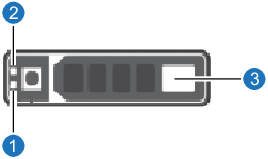
- Drive activity LED indicator
-
Drive status LED indicator
|
Drive status indicator code |
Condition |
|---|---|
| Flashes green twice per second | Identifying drive or preparing for removal. |
| Off |
Drive ready for removal. Note: The drive status indicator remains off until all drives are initialized after the system is turned on. Drives are not ready for removal during this time. |
| Flashes green, amber, and then turns off | Predicted drive failure. |
| Flashes amber four times per second | Drive failed. |
|
Flashes green slowly |
Drive rebuilding. |
|
Solid green |
Drive online. |
|
Flashes green for three seconds, amber for three seconds, and then turns off after six seconds |
Drive rebuild stopped. |
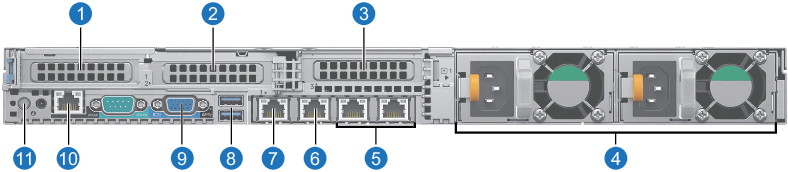
The rear panel of the server node includes the following features and indicators:
|
Item |
Indicator, button, or connector |
Icon |
Description |
|---|---|---|---|
|
1 |
PCIe Slot 1 |
n/a |
The expansion slot(s) enable you to connect PCI Express expansion cards. See Supported expansion cards. |
|
2
|
PCIe Slot 2 |
n/a |
|
| 3 |
PCIe Slot 3 |
n/a | |
| 4 | PSUs (Power Supply Units) | n/a | Two hot-swappable power supplies that provide server power. |
|
5a |
1 GbE Metadata NIC ports |
n/a |
For attaching network connections for server metadata access. |
|
6 |
1 GbE Management NIC port |
n/a |
For accessing StorNext, StorNext Connect, and command line for server management functions over the network. |
|
7 |
1 GbE Service NIC port |
n/a |
For service and support use only. |
|
8 |
USB 3.0 ports |
|
The USB ports are 9-pin and 3.0-compliant. These ports enable you to connect USB devices to the system. |
|
9 |
VGA port |
|
Enables you to connect a display device to the system. |
|
10 |
1 GbE Service NIC port |
n/a |
For service and support use only. |
|
11 |
System identification button |
|
The System Identification (ID) button is available on the front and back of the systems. Press the button to identify a system in a rack by turning on the system ID button. |
|
a Items 5, 6, and 7 are ports of the network daughter card, which is pre-installed in the system. |
|||
|
Note: DO NOT connect anything to the serial port connector on the rear of the system. If something is connected to the serial port, the server will be unable to boot when a reboot is initiated. |
|||

Each NIC on the back panel has indicators that provide information about the activity and link status. The activity LED indicator indicates if
data is flowing through the NIC, and the link LED indicator indicates the speed of the connected network.
NIC Indicators:
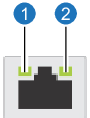
- Link LED indicator
- Activity LED indicator
|
Status |
Condition |
|---|---|
| Link and activity indicators are off | The NIC is not connected to the network. |
| Link indicator is green and activity indicator is blinking green | The NIC is connected to a valid network at its maximum port speed and data is being sent or received. |
| Link indicator is amber and activity indicator is blinking green | The NIC is connected to a valid network at less than its maximum port speed and data is being sent or received. |
| Link indicator is green and activity indicator is off | The NIC is connected to a valid network at its maximum port speed and data is not being sent or received. |
|
Link indicator is amber and activity indicator is off |
The NIC is connected to a valid network at less than its maximum port speed and data is not being sent or received. |
|
Link indicator is blinking green and activity is off |
NIC identify is enabled through the NIC configuration utility. |
AC power supply units (PSUs) have an illuminated translucent handle that serves as an indicator and DC PSUs have an LED that serves as
an indicator. The indicator shows whether power is present or a power fault has occurred.
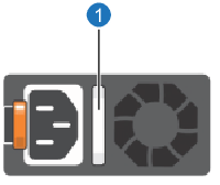
- AC PSU status indicator/handle
|
Power indicator codes |
Condition |
|---|---|
| Green | A valid power source is connected to the PSU and the PSU is operational. |
| Blinking amber | Indicates a problem with the PSU. |
| Blinking green | When the firmware of the PSU is being updated, the PSU handle blinks green. |
| Blinking green and turns off |
When hot-plugging a PSU, the PSU handle blinks green five times at a rate of 4 Hz and turns off. This indicates a PSU mismatch with respect to efficiency, feature set, health status, or supported voltage. |
| Not illuminated | Power is not connected to the PSU. |
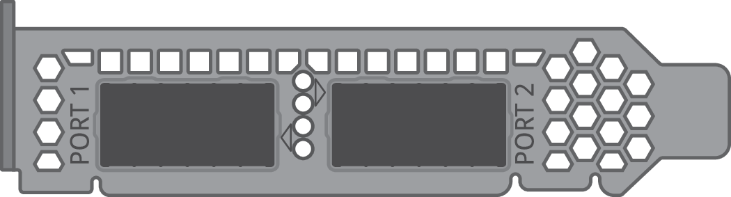
The server has different network and Fibre Channel connection options depending on the expansion cards purchased.
| Expansion Card Description |
Supported Expansion Cards |
|---|---|
|
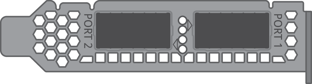
Dual-Port, low-profile, 10/40/25/50/100 GbE NIC Note: Dell/Nvidia Connect X-6 cards require StorNext 7.1.1 or later. Note: Dell/Mellanox Connect X-5 En cards require StorNext 6.2.0 or later. |
|
| Dual-Port 10/25 GbE HBA/HCA with VPI (virtual protocol interconnect), low-profile |
|
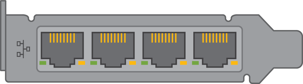
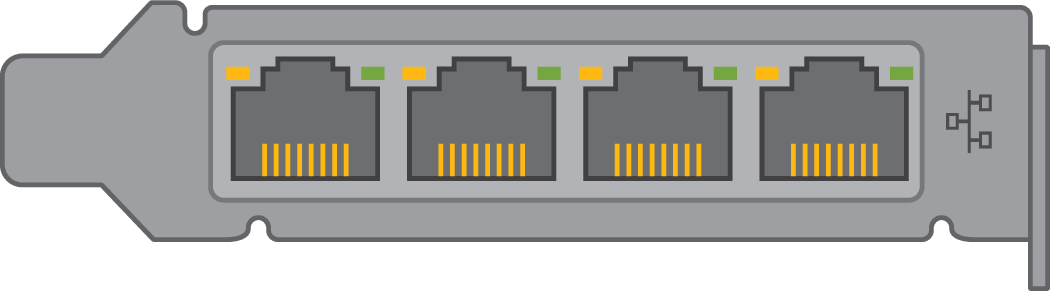
| Quad-Port 10 GbE Base-T NIC, low-profile |
 |
| Empty | (n/a - slot cover installed) |
| Expansion Card Description |
Supported Expansion Cards |
|---|---|
|
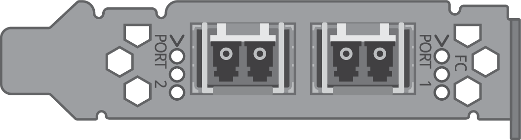
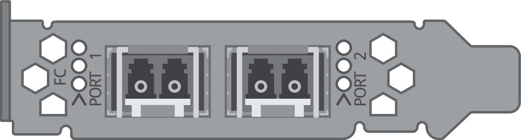
Dual-Port 32 Gb Fibre Channel HBA (shown with SFPs installed), low-profile Note: The Dell/QLogic QLE2772-SR-SP requires StorNext 7.0 or later |
|
|
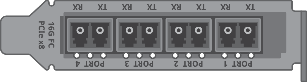
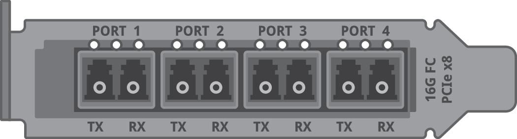
Quad-Port 16 GB Fibre Channel HBA, low-profile Caution: While both tape and disk SAN may be supported on FC HBA cards in some storage environments, in others, the storage configuration may require separate/dedicated tape and disk SAN FC HBA cards (Example: IBM LTO drives using the lin_tape driver). See the documentation for your specific disk and/or tape storage to determine if you must have separate FC HBA cards for disk and tape. |
|
|
Dual-Port, low-profile, 10/40/25/50/100 GbE NIC Note: Dell/Nvidia Connect X-6 cards require StorNext 7.1.1 or later. Note: Dell/Mellanox Connect X-5 En cards require StorNext 6.2.0 or later. |
|
| Dual-Port 10/25 GbE HBA/HCA with VPI (virtual protocol interconnect), low-profile |
|
| Quad-Port 10 GbE base-T NIC, low-profile |
|
| Empty | (n/a - slot cover installed) |
| Expansion Card Description |
Supported Expansion Cards |
|---|---|
|
Dual-Port 32 Gb Fibre Channel HBA (shown with SFPs installed), low-profile Note: The Dell/QLogic QLE2772-SR-SP requires StorNext 7.0 or later |
|
|
Quad-Port 16 GB Fibre Channel HBA, low-profile Caution: While both tape and disk SAN may be supported on FC HBA cards in some storage environments, in others, the storage configuration may require separate/dedicated tape and disk SAN FC HBA cards (Example: IBM LTO drives using the lin_tape driver). See the documentation for your specific disk and/or tape storage to determine if you must have separate FC HBA cards for disk and tape. |
|
|
Dual-Port, low-profile, 10/40/25/50/100 GbE NIC Note: Dell/Nvidia Connect X-6 cards require StorNext 7.1.1 or later. Note: Dell/Mellanox Connect X-5 En cards require StorNext 6.2.0 or later. |
|
You can locate server identification numbers, including the StorNext System Serial Number (SSN) and the Service Tag number, in the following locations:
The StorNext System Serial Number and Service Tag number are located in different locations on the server. The LCD Display Panel, located on the front of the server, displays both the model type and System Serial Number server nodes. In addition, both the System Serial Number and the Service tag number are located in multiple locations on labels on the server chassis as shown in the following image:
|
|||
|
|||
|
|||
|
|||
|
You can use the system command line to access the StorNext System Serial Number.
Steps
- Open an SSH connection to the appropriate server and use the IP address assigned to the node on the Management or LAN Client network, or use the Service Port IP address.
- 10.17.21.1
- Initiate an ssh session to the system using Terminal or PuTTY:
- Log in to the command line using the following credentials:
- User name:
stornext - Password:
<stornext user account password>Note: "
password" is the default password for the stornext user account. If the password has been changed, use the current password. Beginning with StorNext 7.0.2, you must change the default password for the stornext user account. As of StorNext 7.0.2, the first time you log in, you will be prompted to change the password to a different one.
- User name:
- Enter
sudo rootshto gain root user access. - Enter the password for the
stornextuser account again.
- Enter the
cvfsidcommand. - Close the SSH session for the node.
The system returns the following information:
<server_MAC_address> <server_OS> <server_name>
Example:
ECF4BCDECC0E linux 0 xcellis13