Replace a Chassis within a Vehicle
|
|
How to Create a PDF |
Remove a Chassis from a Vehicle
Powering off the system in the vehicle and a system in the data center is the same procedure. However, engineers at a customer site might have a computer within the vehicle that controls the power-off and power-on process.
Note: Engineers at your location might have the central computer within the vehicle programmed to perform a controlled software power-off of the system any time the vehicle is turned off. If that is the case, no need to perform this process to power-off the system in the vehicle.
Additional Information
This is the proper way to perform a controlled software power-off of the system.
- There is a power switch on the back of the system; but, this performs a hard power-off of the system.
- This switch should only be used for an emergency shut-down of the system.
- This type of power-off might cause data loss.
Note: If the OMV/GUI defaults have been changed, use that data to log onto the system.
Complete the following process to "Power-off" the system.
- Access the GUI/OMV.
- Address: 10.0.0.1
- Default Username: admin
- Default Password: password
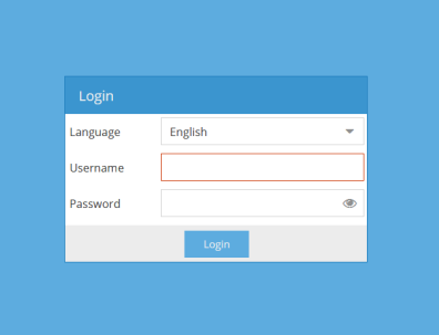
-
Ensure the following screen appears.
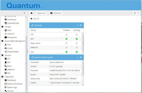
- Select > Pull-down arrow > Shutdown.
-
Ensure the following screen appears.
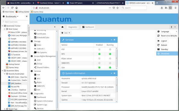
- Ensure the system powers off in 2-3 minutes.
Caution: The 10 mounting holes on the sides of the system are 8/32 threads and have self-clinching nuts. Internal penetration of mounting screw must not exceed .210 inches. Using "capped" pemnuts is not feasible.
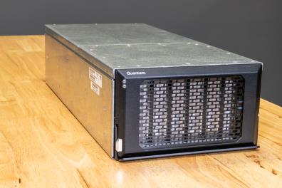
Note: The chassis has an internal power supply, fan, and circuit boards. These units are not CRUs and must remain with the chassis.
The CRUs within the chassis must be removed (with applicable cables); the CRUs are:
- Drive magazine
- Six drives installed
- Drives can be: 2.5" SSDs or 3.5" HDDs
- Applicable cables are shipped with the system.
To remove the chassis from the vehicle, complete the following steps.
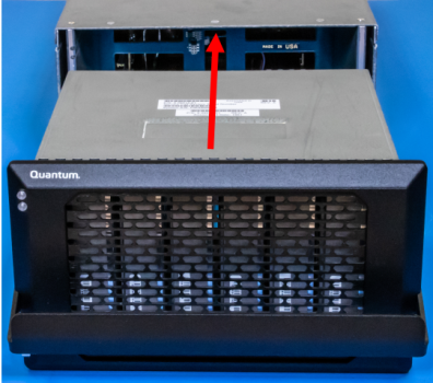
- Remove the drive magazine from chassis.
-
Locate the quick-release lock (Callout 3) on the front-left side of the drive magazine handle.
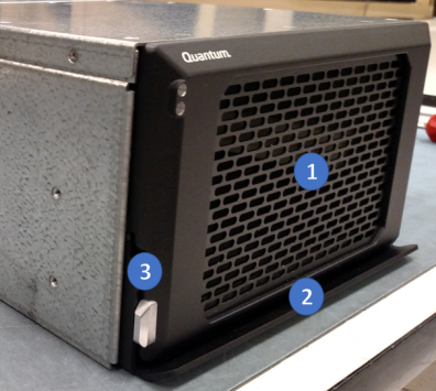
Item Description 1 Drive Magazine 2 Handle 3 Quick-Release Lock -
Depress the quick-release lock and the handle will disengage from the chassis.
Note: This allows the drive magazine to be removed.
-
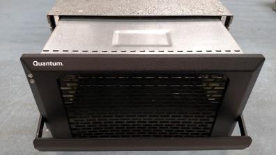
Lift up on the handle and slide the drive magazine partially out of the chassis.
-
Use one hand to pull the drive magazine from the chassis and use the other hand to support the drive magazine as you remove it from the chassis.
- Place the drive magazine on an ESD mat.
- Label the cables at the rear of the chassis; see figure and table below.
-
Disconnect the cables at the rear of the chassis.
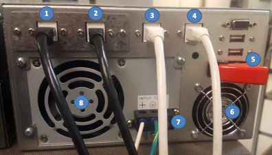
Item Description 1 10GbE Port 1 2 10GbE Port 2 3 GbE IPMI 4 GbE GUI 5 Power Switch 6 Fan 7 12 VDC 8 Fan -
Remove the applicable hardware that secures the chassis within the vehicle.
- The chassis has a number of mounting holes on the sides of the unit.
- The customer uses these mounting holes to attach applicable hardware to secure the system within the vehicle.
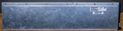
 Mounting Holes (Left Side)
Refer to the below figure for the Mounting holes on the left side of the system.
Mounting Holes (Right Side)
Refer to the below figure for the mounting holes on the right side of the system.

- Remove the chassis from the vehicle and place on an ESD mat.
Install a Chassis within a Vehicle
Note: The chassis has an internal power supply, fan, and circuit boards. These units are not CRUs and must remain with the chassis.
The following CRUs must be installed within the chassis (with applicable cables) after the chassis is installed into the vehicle; the CRUs are:
- Drive magazine
- Six drives installed
- Drives can be: 2.5" SSDs or 3.5" HDDs
- Applicable cables are shipped with the system.
To install the chassis into the vehicle, complete the following steps.
-
Install the applicable hardware that secures the chassis within the vehicle.
- The chassis has a number of mounting holes on the sides of the unit.
- The customer uses these mounting holes to attach applicable hardware to secure the system within the vehicle.
- Refer to Mounting Holes (Left Side) and Mounting Holes (Right Side) for location of the mounting holes in the system.
Mounting Holes (Left Side)
Refer to the below figure for the mounting holes on the left side of the system.
 Mounting Holes (Right Side)
Refer to the below figure for the mounting holes on the right side of the system.
-
Use one hand to slide the drive magazine into the chassis and use the other hand to support the drive magazine as you install it into the chassis.
-
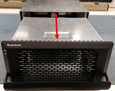
Lift up on the handle and slide the drive magazine partially into the chassis.
- Keep the handle in the up position and slide the drive magazine into the chassis until it stops.
-
Rotate the handle down and ensure the quick-release lock (Callout 3) on the front-left side of the drive magazine handle engages (locks the drive magazine into the chassis).
Item Description 1 Drive Magazine 2 Handle 3 Quick-Release Lock Note: All cables should be marked as identified in the figure below.
-
Connect all the cables at the rear of the chassis.
Item Description 1 10GbE Port 1 2 10GbE Port 2 3 GbE IPMI 4 GbE GUI 5 Power Switch 6 Fan 7 12 VDC 8 Fan
That completes the installation of the chassis within the vehicle.
You must power-on the system after installation, if a CRU has been replaced, or if the system was shutdown.
Note: Once power is applied to the system, the system might power up automatically. The power switch is always in the normal "ON" position on the back of the system. If the system does not power up, refer to the following steps.
Complete the following to power on the system.
-
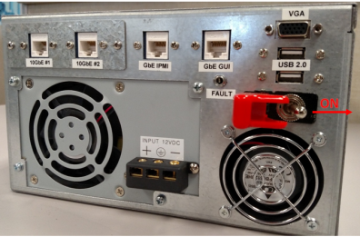
Locate the power switch (Callout 5) on the back of the system.
Item Description 1 10GbE Port 1 2 10GbE Port 2 3 GbE IPMI 4 GbE GUI 5 Power Switch 6 Fan 7 12 VDC 8 Power Supply -
Flip the red-cover up on the power switch to access the toggle switch.
-
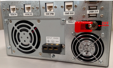
Move the power switch to the "OFF" position (to left).
-
Move the power switch to the "ON" position (to right).
-
Flip the red-cover down on the power switch.
Item Description 1 10GbE Port 1 2 10GbE Port 2 3 GbE IPMI 4 GbE GUI 5 Power Switch 6 Fan 7 12 VDC 8 Power Supply
The following events occur:
- The fan in the power supply and the fan begins to spin.
- The green light on the front (top-left) of the system illuminates.

- The system boots up (initializes) within approximately two (2) minutes.
Note: The blue light on the front of the system blinks when data is transferred to/from the system.