Power Off the System
Powering off the system in the vehicle and a system in the data center is the same procedure. However, engineers at a customer site might have a computer within the vehicle that controls the power-off and power-on process.
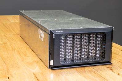
Note: Engineers at your location might have the central computer within the vehicle programmed to perform a controlled software power-off of the system any time the vehicle is turned off. If that is the case, no need to perform this process to power-off the system in the vehicle.
Additional Information
This is the proper way to perform a controlled software power-off of the system.
- There is a power switch on the back of the system; but, this performs a hard power-off of the system.
- This switch should only be used for an emergency shut-down of the system.
- This type of power-off might cause data loss.
Note: If the OMV/GUI defaults have been changed, use that data to log onto the system.
Complete the following process to "Power-off" the system.
- Access the GUI/OMV.
- Address: 10.0.0.1
- Default Username: admin
- Default Password: password
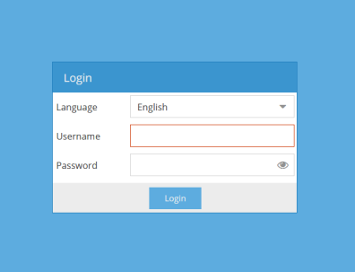
-
Ensure the following screen appears.
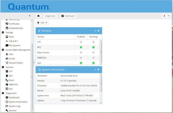
- Select > Pull-down arrow > Shutdown.
-
Ensure the following screen appears.
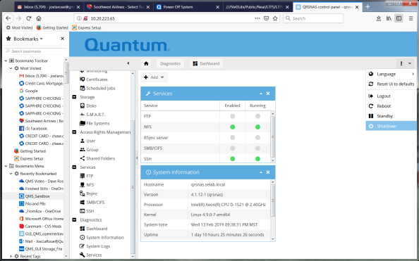
- Ensure the system powers off in 2-3 minutes.
Complete the following procedure to attach to the IPMI port on the back of the system:
Additional Information
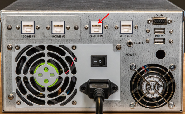
- You must access the IPMI through the IPMI port on the back of the system. You can power on or power off the system (in vehicle or in data center) using IPMI.
- We are using a representative AC system to perform this procedure.
-
Locate the IPMI port on the back of the system.
-
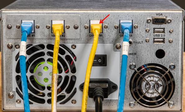
Connect an Ethernet cable from your computer to the IPMI port on the back of the system.
- Set up your computer so that you can communicate with the system.
Note: If the system IPMI address has been changed at your company, enter the applicable address, username, and password. If it has not been changed, use the information below.
Complete the following process to power off the system.
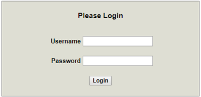
- Access the IPMI:
- Default Address:
10.17.21.51 - Default Username:
admin - Default Password:
Qa@Ip00!(the entry after @ is a capital "I", as in India)
- Default Address:
-
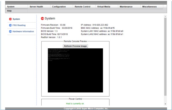
Verify that the following screen appears (IPMI opening screen).
-
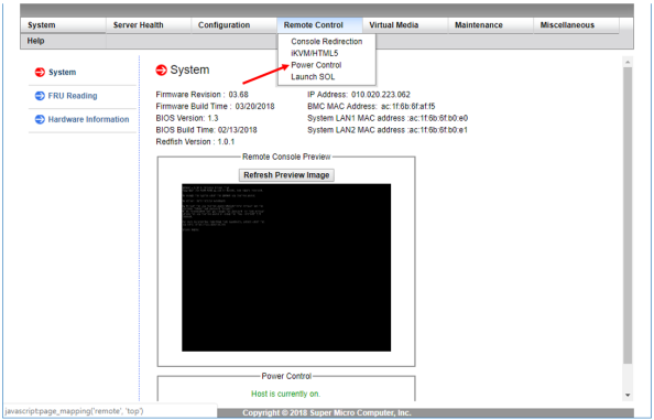
Click the "Remote Control" tab at the top of the screen.

-
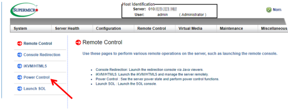
Click on the "Power Control" selection in the "Remote Control" tab.
-
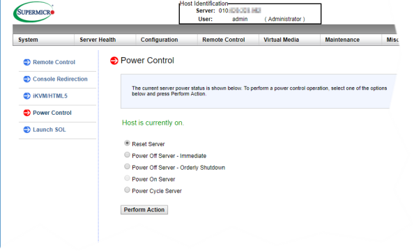
Verify that the "Power Control" screen appears.
Radio Button selections include:
- Reset Power
- Power Off Server - Immediate (similar to an EPO: emergency power off)
- Power Off Server - Orderly Shutdown (recommended)
- Power On Server
- Power Cycle Server
-
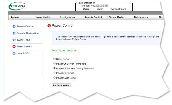
When the "Power Control" screen appears, click the "Power Off Server - Orderly Shutdown" radio button to power-off the system.
-
After your selection, Power Off Server - Orderly Shutdown, click on the "Perform Action" selection to initiate system orderly shutdown.
Note: While the system is powering off, the word "LOADING" appears in the top right corner of the screen.
- Verify that the below "Power Control" screen appears when the system powers off.
- Notice the message "Host is currently off." in the middle of the screen.
- The Power Control radio buttons default to "Power On Server".
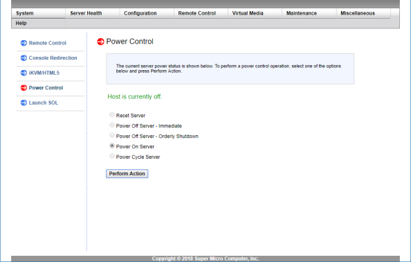
That completes the process of powering off the system using IPMI.
There is a power switch on the back of the system; but, this performs a hard power-off of the system.
- This switch should only be used for an emergency shut-down of the system.
- This type of power-off might cause data loss.
Complete the following to power off the system.
-
Locate the power switch (Callout 5) on the back of the system.
Note: The figure below is a DC system (notice the input 12VDC label).
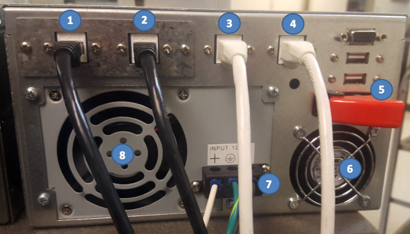
Item Description 1 10GbE RJ-45 Data Port 1 2 10GbE RJ-45 Data Port 2 3 IPMI RJ-45 1GbE Port 4 GUI RJ-45 1GbE Port 5 Power Switch 6 Chassis Cooling Fan 7 12 VDC 8 Power Supply Note: The figure below is an AC system (notice the AC power cord).
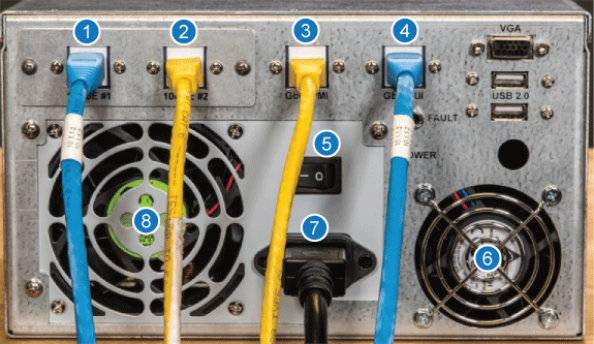
Item Description 1 10GbE RJ-45 Data Port 1 2 10GbE RJ-45 Data Port 2 3 IPMI RJ-45 1GbE Port 4 GUI RJ-45 1GbE Port 5 Power Switch 6 Chassis Cooling Fan 7 100-240 VAC 8 Power Supply -
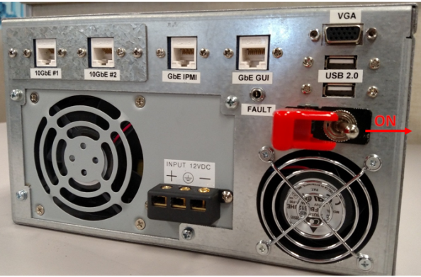
Flip the red-cover up on the power switch to access the toggle switch on a DC system. The AC system has no cover over the power switch.
Note: The figure below is a DC system (notice the input 12VDC label).
Note: The figure below is an AC system (notice the AC power cord).
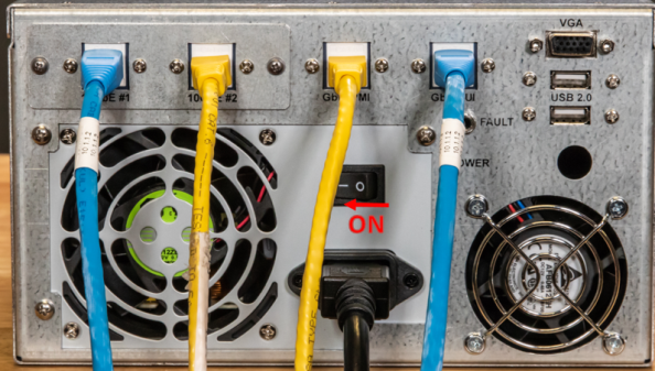
-
Move the power switch to the "OFF" position (to left) on the DC system.
Note: The figure below is a DC system (notice the input 12VDC label).
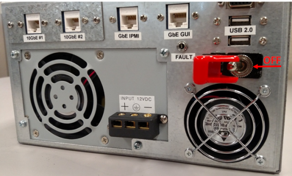
-
Move the power switch to the "OFF" position (to right) on the AC system.
Note: The figure below is an AC system (notice the AC power cord).
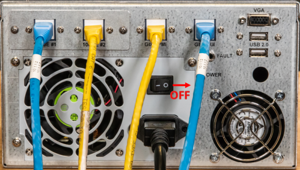
- Ensure the system powers off instantly.

