Hardware Overview
|
|
How to Create a PDF |
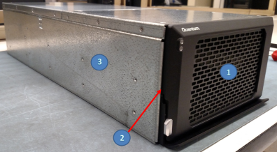
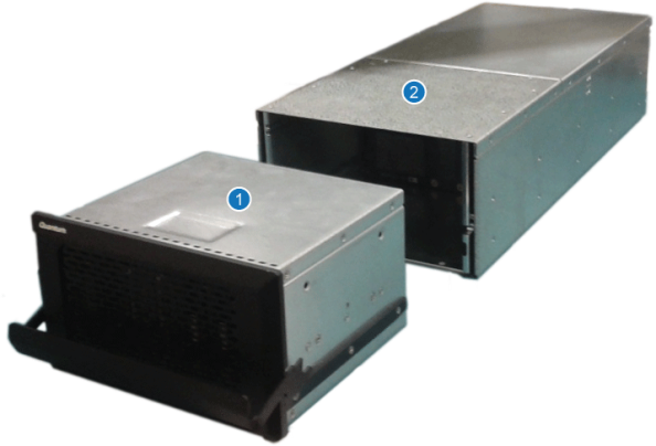
| Item | Description |
|---|---|
| 1 | Drive Magazine |
| 2 | Drives (6 drives each in Drive Magazine) |
| 3 | Chassis |
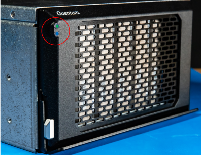
The R3000 system has two LEDs located on the front of the unit. Refer to figure below for the location of the LEDs.
The LEDs illuminate as follows:
| LED | Description |
|---|---|
| Green (top LED) | Illuminates when the system is powered on. The system boots up (initializes) within approximately 2.5 minutes and the power supply/system fans begin to spin. |
| Blue (bottom LED) | Blinks when data is transferred to/from the system. |
The R3000 system has a "Fault port/receptacle" on the rear of the unit (see image below).
The "Fault port/receptacle" on the rear of the unit:
- Is not used within the data center.
- Can be used within vehicle with proper cabling, to a light within the vehicle to identify system faults.
- Customers must install this cabling and light, if this function is desired.
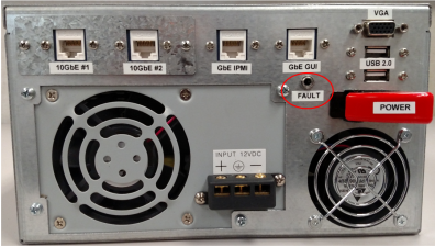
The R3000 DC chassis is shown below
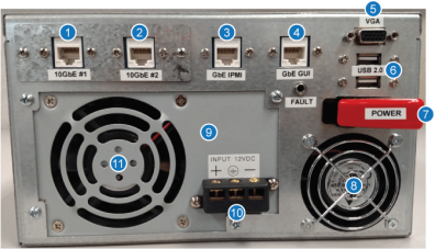
| Item | Description |
|---|---|
| 1 | 10GbE RJ-45 Data Port 1 |
| 2 | 10GbE RJ-45 Data Port 2 |
| 3 | IPMI RJ-45 1GbE Port |
| 4 | GUI RJ-45 1GbE Port |
| 5 | VGA Port |
| 6 | Two USB Ports |
| 7 | Power Switch |
| 8 | Chassis Cooling Fan |
| 9 | Power Supply (contains switch, receptacle, and fan) |
| 10 | Power Receptacle |
| 11 | Power Supply Cooling Fan |
The AC chassis is shown below.

| Item | Description |
|---|---|
| 1 | 10GbE RJ-45 Data Port 1 |
| 2 | 10GbE RJ-45 Data Port 1 |
| 3 | IPMI RJ-45 1GbE Port |
| 4 | GUI RJ-45 1GbE Port |
| 5 | VGA Port |
| 6 | Two USB Ports |
| 7 | Power Switch |
| 8 | Chassis Cooling Fan |
| 9 | Power Supply (contains switch, receptacle, and fan) |
| 10 | Power Receptacle |
| 11 | Power Supply Cooling Fan |
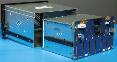
The drive magazine in removed and installed at the front of the chassis.
Caution: Always use the "transport case" (pelican case) to transfer the drive magazine(s) to/from the vehicle and/or to/from the data center. Use two hands to carry the drive magazine. Do not use the handle to carry the drive magazine; you might drop the drive magazine, damage it, and could lose system data.
| Item | Description |
|---|---|
| 1 | Drive Magazine |
| 2 | Chassis |
Additional Information
- The magazine uses a handle, with a quick-release lock, to unlock and lock the unit into the chassis.
- The magazine is easily removed so that its data can be transferred to the data center immediately.
- The magazine contains six (6) 3.5 inch HDDs or 2.5 inch SSDs.
- The magazine ships with the six drives configured as a RAID 5.
- The magazine has a depth of 7 inches (17.78 cm).
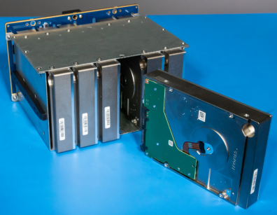
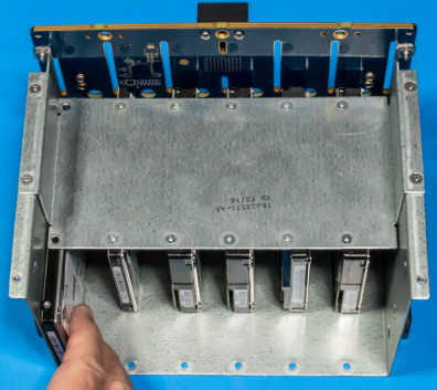
The drive magazine houses the drive assembly.
Note: In the event of a drive failure, the drive assembly must be removed from the drive magazine so as to remove and replace the failed drive.
| Item | Description |
|---|---|
| 1 | Drive Assembly |
| 2 | Drive Magazine |
Additional Information
- The drive assembly contains the drives (2.5 inch or 3.5 inch) and the PCBA that provides connection to the chassis motherboard.
- The 2.5 inch drive assembly differs slightly from the 3.5 inch drive assembly.
- The 2.5 inch drive assembly uses an adapter plate to secure the drive within the drive assembly.
The drive assembly contains six (6) 2.5 inch SSDs or 3.5 inch HDDs .
Note: SSDs and HDDs cannot be mixed in any of the drive assemblies.
The 2.5 inch drives are shown below (representative example only), with one drive partially removed from the drive assembly.
The 3.5 inch drives are shown below, with one drive removed from the drive assembly.