F1000 Hardware Overview
The Quantum F1000 is an ultra-fast storage array for editing, rendering, and processing of video content and other large, unstructured data sets in a shared storage environment. The F1000 RAID configuration is based on Quantum's Cloud Storage Platform—a software-defined block storage stack tuned specifically for video and video-like data.
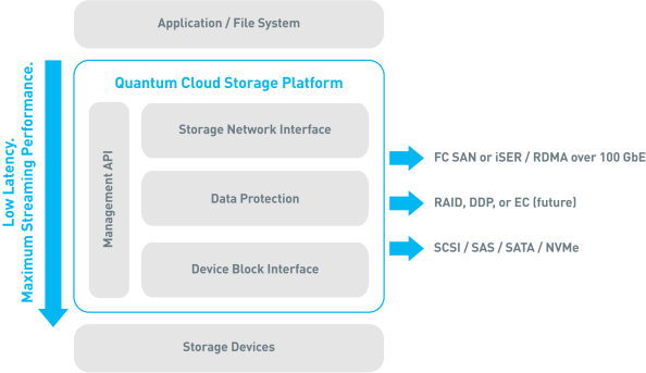
The F1000 is designed to be part of StorNext shared storage environment, and it is supported by the following host software interfaces:
- StorNext – see the StorNext 6 Documentation Center
- Appliance Controller – see the Appliance Controller Documentation Center
Additionally, it is available in an FC or Ethernet interface configuration:
Storage Capacities
The F1000 contains ten NVMe U.2 SSDs. It is available in two capacity points, as detailed below.
|
SSD Quantity |
Raw System Capacity |
SSD Size |
|
10 |
38.4 TB |
7.68 TB |
|
10 |
76.8 TB |
15.36 TB |
LUN Configuration
The F1000 is designed for a StorNext shared storage environment. It is pre-configured with two logical unit numbers (LUNs) in a RAID10 configuration and is optimized for high-resolution workflows.
Note: Do not change the pre-configured LUNs.
The LUNs are intended for data storage, not metadata storage. It is recommended to use a separate storage array for metadata storage.
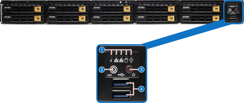
The front of the F1000 consists of ten NVMe SSD drive bays, and a control panel. The control panel is detailed below.

|
Item |
Component |
|
1 |
NVME (non-volatile memory express) U.2 SSD hot-swap data drives (qty. 10) |
|
2 |
Control panel |
| Item | Description | Function |
|---|---|---|
|
1 |
LEDs |
Generally, the LEDs indicate system activity and health. See Front LEDs for more information. |
|
2 |
UID Button |
Unit Identification (UID) button. Press it to turn on or off the blue UID LED in the control panel (see Front LEDs for more information), and a blue LED on the rear panel of the chassis (see Back LEDs for more information). These are used to locate the server in large racks, and to provide information about system health. |
|
3 |
Power Button |
Main power switch. Applies or removes primary power from the power supply to the server, but maintains standby power. |
|
4 |
USB 3.0 Port |
Keyboard or mouse ports. |

|
Item |
Component |
|
1 |
700-750W PSUs (power supply units; qty. 2) |
|
2 |
Ports and LED |
|
3 |
Full-height PCIe slots (qty. 2) |
Note: The F1000 does not support installing a combination of both Fibre Channel cards and Ethernet cards in the same system. The system is available in either a Fibre Channel configuration (2 FC cards; system total of eight FC ports), or Ethernet configuration (2 100 GbE cards; system total of four 100 GbE Eth ports)

|
Item |
Description |
|
1 |
Low-profile PCIe slot (empty) |
|
2 |
Full-height PCIe 3.0 x 16 slot. This slot can contain one of the following cards:
|
|
3 |
Full-height PCIe 3.0 x 16 slot. This slot can contain one of the following cards:
|
See the diagram below for an explanation of F1000 ports, LEDs, and the UID switch.

|
Item |
Component |
|
1 |
Power Supply LEDs See Rear LEDs for more information. |
|
2 |
VGA port Console port video output connector |
|
3 |
IPMI LAN port Accepts RJ45 cables |
|
4 |
Keyboard or mouse USB 3.0 ports |
|
5 |
1 GbE LAN port #1 (M1P1) Accepts RJ45 cables. |
|
6 |
1 GbE LAN port #2 (M1P2) Accepts RJ45 cables. |
|
7 |
UID switch Turn this switch to On to illuminate the front and back UID LEDs. The default position is Off. |
|
8 |
UID LED See Rear LEDs for more information. |
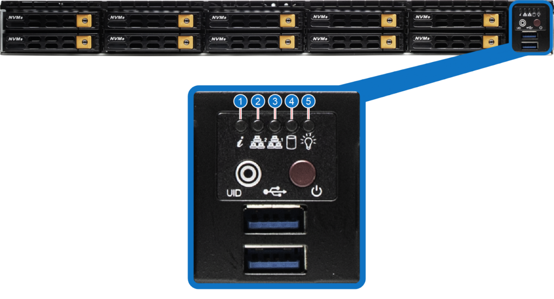
LEDs on the front of the F1000 are located on the control panel.
| Item | LED | Action |
|---|---|---|
|
1 |
Unit Identification (UID) |
This LED is activated by the UID button (in the front of the F1000) or the UID switch (in the back of the F1000).
|
|
2 |
NIC1 |
When flashing, indicates GLAN1 activity. Note: This LED corresponds to the network port. |
|
3 |
NIC2 |
When flashing, indicates GLAN2 activity. Note: This LED corresponds to the network port. |
|
4 |
SSD |
When flashing, indicates drive activity. |
|
5 |
Power |
Indicates power supplied to the system's power supply units. This LED illuminates when the system is operating normally. |

| Item | LED | Action |
|---|---|---|
|
1 |
Power Supply |
|
| 2 | LAN port—Link |
|
| 3 | LAN port—Activity |
|
|
4 |
Unit Identification (UID) |
This LED is activated by the UID button, which is part of the control panel on the front of the unit. See F1000 Front for more information. It is also activated by the UID switch, which is on the back of the unit.
|
The F1000 array can include one of the following Fibre Channel (FC) or Ethernet interface card configurations.
Note: The F1000 is not available with both FC cards and Ethernet cards installed in the same system.
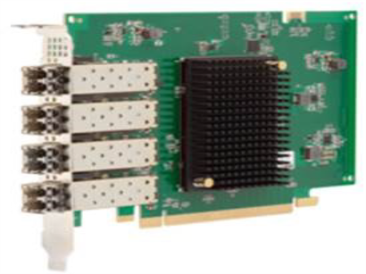
2 x 32 Gb FC, Quad-Port, Emulex LPe35004-S3
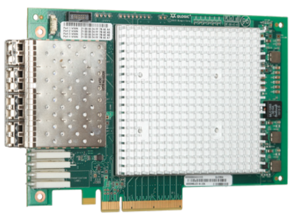
2 x 32 Gb FC, Quad-Port, Marvell QLogic QLE2764-SR-CK
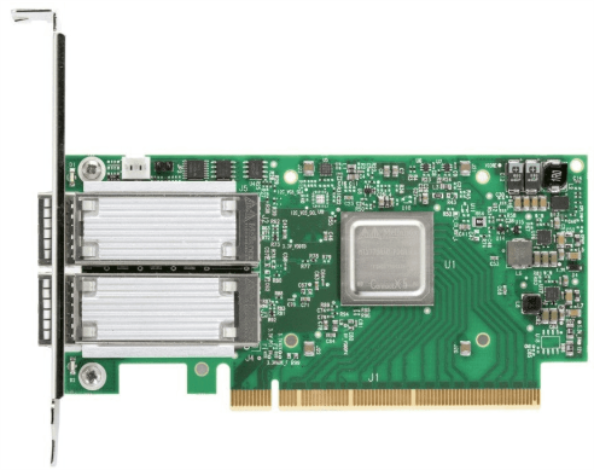
2 x 100 GbE, Dual-Port, Mellanox ConnectX-5 cards
