Installing the Optional Interface Cards
DXi6800, DXi6902, and DXi6900 G1 Cards
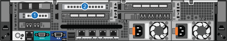
Figure 1: DXi6800 and DXi6900 G1 Optional Card Location
| Item | Card Option(s) |
|---|---|
| 1 | Install optional i350 or X520 network card in slot 2. See Table 1 for configuration options. |
| 2 | (DXi6900 G1 only) Install optional X540 network card in slot 4. See Table 1 for configuration options. |
Table 1: DXi6800, DXi6902, DXi6900 G1 Network Card Configuration Options
| Option | PCI Slot 2 | PCI Slot 4 |
|---|---|---|
| 101 | 2 x 10 Gb Ethernet | |
| 102 | 4 x 1 Gb Ethernet | |
| 103 | 2 x 10 GBase-T Ethernet (DXi6900 G1 only) |
DXi6900 G2 and DXi6900-S Cards
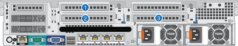
Figure 2: DXi6900 G2 and DXi6900-S Optional Card Location
| Item | Card Option(s) |
|---|---|
| 1 | Install optional X520, X540, or Fibre Channel card in slot 4. See Table 2 for configuration options. |
| 2 | Install optional X520, X540, or Fibre Channel card in slot 5. See Table 2 for configuration options. |
| 3 | Install optional X520, X540, or Fibre Channel card in slot 7. See Table 2 for configuration options. |
Table 2: DXi6900 G2 Network Card Configuration Options
Caution: The PCI slot location for each card must be followed in each configuration option.
| PCI Slot 4 | PCI Slot 5 | PCI Slot 7 |
|---|---|---|
| Not Used | 2 x 16 Gb Fibre Channel | Not Used |
| Not Used | 2 x 16 Gb Fibre Channel | 2 x 16 Gb Fibre Channel |
| 2 x 16 Gb Fibre Channel | 2 x 16 Gb Fibre Channel | 2 x 16 Gb Fibre Channel |
| 2 x 10 Gb Ethernet * | Not Used | Not Used |
| 2 x 10 Gb Ethernet * | Not Used | 2 x 10 Gb Ethernet * |
| 2 x 10 Gb Ethernet * | 2 x 10 Gb Ethernet * | 2 x 10 Gb Ethernet * |
| 2 x 10 Gb Ethernet * | 2 x 16 Gb Fibre Channel | Not Used |
| 2 x 10 Gb Ethernet * | 2 x 16 Gb Fibre Channel | 2 x 16 Gb Fibre Channel |
| 2 x 10 Gb Ethernet * | 2 x 16 Gb Fibre Channel | 2 x 10 Gb Ethernet * |
|
* 2 x 10 Gb Ethernet = 2 x 10 GbE (SFP+) or 2 x 10 GBase-T Ethernet ports |
||
DXi6800 / DXi6902 / DXi6900 G1: Installing Optional Cards
To install the optional i350 or X520 network card in the DXi6800, DXi6902, and DXi6900 G1 Node:
Caution: Use appropriate ESD precautions, including the use of a grounding strap, when performing this procedure.
-
Holding the touch points, lift the expansion card riser 1 from the riser connector on the system board (see Figure 3).
Figure 3: Removing and Installing the Expansion Card Riser 1
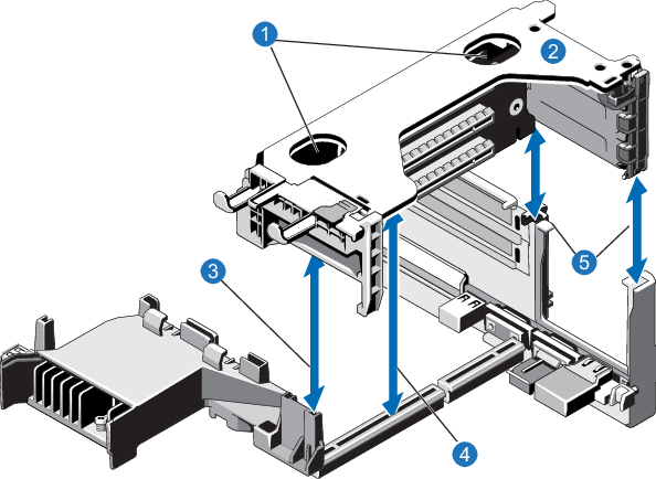
Item
Description
1
Touch points 2
Expansion card riser 1 3
Front riser guide 4
Expansion card riser 1 connector 5
Back riser -
Press the tab to release the expansion card latch and rotate the latch away from the expansion card riser (see Figure 4).
Figure 4: Installing the Optional Network Card in Riser 1
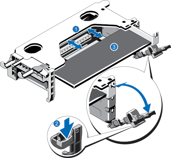
1. Expansion card connector 2. Expansion card latch tab 3. Network Card -
Remove the metal slot cover from slot 2 by sliding it out of the slot.
- Holding the optional network card by its edges, position the card so that the card edge connector aligns with the expansion card connector.
- Insert the card edge connector firmly into the expansion card connector until the card is fully seated.
- Close the expansion card latch.
- Holding the touch points, insert the expansion card riser 1 into the riser connector on the system board (see Figure 3).
- (Optical 10 GbE option only) Insert an SFP+ unit into each 10 GbE port on the X520 card. (The SFP+ units are included with the optional 10 GbE network card.)
To install the optional X540 network card in the DXi6900 G1 Node:
Caution: Use appropriate ESD precautions, including the use of a grounding strap, when performing this procedure.
-
Lift the expansion card latch out of the slot (see Figure 5).
The expansion card latch is located to the right of PCIe slots as you face the rear of the Node. The latch will remain attached to the system.
Figure 5: Installing an Optional Card in Riser 2
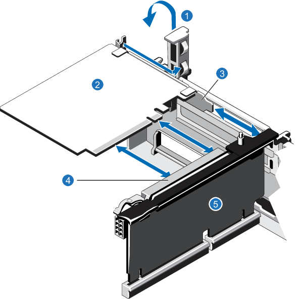
1. Expansion card latch (blue) 2. Network card 3. Metal slot cover 4. Expansion card connector 5. Expansion card riser 2 - Remove the metal slot covers from the slots by sliding it out of the slot.
- Holding the network card by its edges, position the card so that the connector on the card aligns with the expansion card connector on the riser.
- Insert the card-edge connector firmly into the expansion card connector until the card is fully seated.
- Push the expansion card latch down to lock the card in place.
DXi6900 G2 and DXi6900-S: Installing Optional Cards
To install an optional X520, X540, or 16 GB Fibre Channel card in the DXi6900 G2 and DXi6900-S Node:
Caution: Use appropriate ESD precautions, including the use of a grounding strap, when performing this procedure.
-
Lift the expansion card latch out of the slot (see Figure 5).
The expansion card latch is located to the right of PCIe slots as you face the rear of the Node. The latch will remain attached to the system.
Figure 6: Installing an Optional Card in Riser 2 or 3
1. Expansion card latch (blue) 2. Network card 3. Metal slot cover 4. Expansion card connector 5. Expansion card riser 2 or 3 - Remove the metal slot covers from the slots by sliding it out of the slot.
- Holding the network card by its edges, position the card so that the connector on the card aligns with the expansion card connector on the riser.
- Insert the card-edge connector firmly into the expansion card connector until the card is fully seated.
- Push the expansion card latch down to lock the card in place.
- (Optical 10 GbE option only) Insert an SFP+ unit into each 10 GbE port on the X520 card. (The SFP+ units are included with the optional 10 GbE network card.)