DXi4800 System Installation
Overview
This guide provides hardware installation and initial system configuration instructions for the Quantum DXi4800 disk backup system. For more information, see the Quantum DXi4800 User's Guide.
Watch the DXi4800 Installation and Initial Configuration below video to get a high-level overview of the installation process. Additional training options are available in the Training Resources and Videos menu options in the DXi4800 Documentation Center.
Note: Your DXi4800 has been configured at Quantum and the components in your Node are listed on a label on the Node outer box. Please review this list to confirm your system's components.

The Quantum DXi4800 can be ordered in the following configurations:
| Licensed Usable Capacity (TB)1 |
System Memory (GB) |
Memory DIMMs (16 GB SR x 8) |
Gen 2 Expansion Modules (JBODs)3 |
Total Rack Space Required |
|---|---|---|---|---|
|
8 - 11² |
96 | 6 | 0 | 2U |
| 16 - 19 | 96 | 6 | 0 | 2U |
| 24 - 27 | 96 | 6 | 0 | 2U |
| 45 | 96 | 6 | 1 | 4U |
| 63 | 96 | 6 | 1 | 4U |
| 81 | 96 | 6 | 1 | 4U |
| 99 | 96 | 6 | 1 | 4U |
| 117 | 96 | 6 | 2 | 6U |
| 135 | 96 | 6 | 2 | 6U |
| 153 | 96 | 6 | 2 | 6U |
| 171 | 96 | 6 | 2 | 6U |
| 189 | 160 | 10 | 3 | 8U |
| 207 | 160 | 10 | 3 | 8U |
| 225 | 160 | 10 | 3 | 8U |
| 243 | 160 | 10 | 3 | 8U |
| 261 | 160 | 10 | 4 | 10U |
| 279 | 160 | 10 | 4 | 10U |
| 297 | 160 | 10 | 4 | 10U |
|
315 (Max Capacity) |
160 | 10 | 4 | 10U |
| 1All capacity licenses are factory installed for initial orders. To purchase a storage capacity upgrade license, contact your Quantum sales representative. After you obtain the storage capacity license, see License Keys in the DXi4800 User’s Guide for instructions on completing the capacity upgrade. | ||||
| 21 TB = 1,000,000,000,000 bytes. | ||||
| 312 x 8 TB HDDs installed in each JBOD. | ||||
Note: Usable space is presented as a decimal (1000) value (TB or Terabyte) in the DXi GUI. Backup applications may report the binary (1024) value (TiB or Tebibyte) but incorrectly label it as "TB". For example, 172 TB will be seen in the DXi GUI; however a backup application may report 146.43 TB. (146.43 "tebibyte (TiB) = 161.001488 "terabyte (TB)")
Note: While the format of the DXi4800 Documentation Center shown in the video differs from the current Documentation Center, the DXi4800 content and navigation are the same.
1. Choose a Location
Quantum recommends installing the system in a controlled or restricted area to prevent access by untrained personnel. In addition, Quantum recommends that system installation be performed only by qualified IT personnel.
When choosing an installation site for the DXi4800 system, consider the following requirements:
Review DXi4800 Site Planning to ensure that your site meets the installation requirements for the DXi4800.
| Physical Characteristics | ||
|---|---|---|
|
|
Node |
Expansion Module (JBOD) |
|
Height |
2U 3.42 in. 8.68 cm |
3.39 in 8.7cm |
|
Width (side to side) |
17.1 in. 43.4 cm |
18.8 in 8.2 cm |
|
Depth (front to back) |
26.7 in. 67.8 cm |
29.1 in 54.1 cm |
|
Weight (stand alone) |
72.9 lbs 33.1 kg |
63.0 lbs 28.6 kg |
|
Rack Space Required |
2U |
2U |
|
Air Clearance |
Open 4 in (10.2 cm) behind unit for proper air flow |
|
The installation site must have the following environmental conditions:
|
Humidity |
|
|
Temperature |
|
|
Altitude |
|
2. Prepare for the Installation
WARNING: To prevent the risk of electrical shock, bodily injury, or damage to the equipment, read all instructions and warnings in the Product Information Guide that shipped with your system.
Before you begin the installation procedure, make the preparations described in the following sections:
The following tools are required for unpacking and installing the DXi4800 system:
- #2 Phillips screwdriver
- Small flat head screwdriver
- Notebook computer
Some components within the DXi4800 system contain static-sensitive parts. To avoid damaging these parts while performing installation procedures, always observe the following precautions:
- Keep the system turned off during all installation procedures.
- Keep static-sensitive parts in their original shipping containers until ready for installation.
- Do not place static-sensitive parts on a metal surface. Place them inside their protective shipping bag or on an anti-static mat.
- Wear anti-static wrist bands when unpacking and handling the units, and avoid touching connectors and other components.
Note: Dry climates and cold-weather heating environments have lower relative humidity and are more likely to produce static electricity.
Depending on the configuration, DXi4800 system components ship in one or more boxes. Each box includes a label that notes the number of the box and the total number of boxes in the shipment (for example, box 1 of 3).
IMPORTANT INFORMATION
- MAKE SURE THAT YOU HAVE ALL BOXES IN THE SHIPMENT BEFORE YOU BEGIN THE INSTALLATION.
- YOU MUST INSTALL THE NODE AND EXPANSION MODULE(S) IN THE RACK, AND CONNECT ALL CABLES BEFORE FOLLOWING THE POWER-UP SEQUENCE.
3. Unpack the DXi4800
By following these unpacking instructions, you help ensure that the system will continue to be safeguarded after it arrives at the installation site:
Note: Make sure to retain all packing materials, as well as the documentation and other items included in the shipping box. The packaging materials must be used if the system is relocated.
The DXi4800 Node box contains rack mount rails with cable management straps, a standard Node Accessory Kit and the DXi4800 Node.
Node Accessory Kit
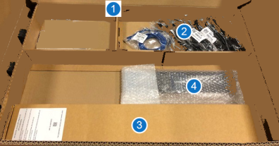
DXi4800 Node
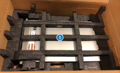
| Item | Description |
|---|---|
| 1 |
Accessory Kit - Includes:
|
| 2 | Base Node Kit |
| 3 | Rack Rails |
| 4 | Node Bezel |
| 5 | DXi Node - Includes the following as ordered:
|
Carefully unpack and remove the components from the packing materials.
For each Expansion module in your system configuration, carefully unpack and remove the components from the packing materials.
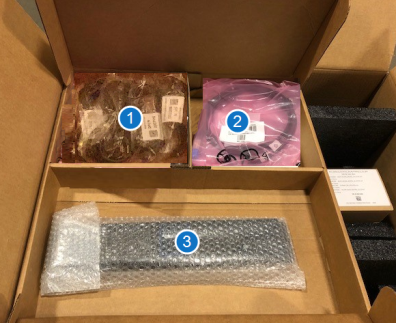
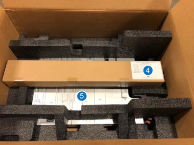
| Item | Description |
|---|---|
| 1 |
C13 to C14 power cord (2), North American power cord (2) |
| 2 | SAS interconnect cable (1m) (2) |
| 3 | Bezel |
| 4 | Rack mount rails |
| 5 | Expansion module (JBOD) |
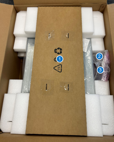
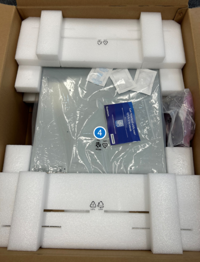
| Item | Description |
|---|---|
| 1 |
Rack mount rails |
| 2 | SAS interconnect cable (1m) (2) |
| 3 | C13 to C14 power cord (2), North American power cord (2) |
| 4 | Expansion module (JBOD) |
4. Install the DXi4800 System in the Rack
Installing the DXi4800 in a rack consists of the following steps:
Component Installation Recommendations
To make it easier to correctly cable the system, and for safety reasons, follow these recommendations when installing the DXi4800 system in the rack:
-
When installing components, start with the lowest Expansion module in the configuration, and then proceed upward in the rack as you add additional components.
-
Make sure to leave enough space below the lowest installed component for future system expansion. The DXi4800 can be expanded to a maximum configuration requiring 10U of rack space.
Recommended Component Rack Order (Maximum Configuration)
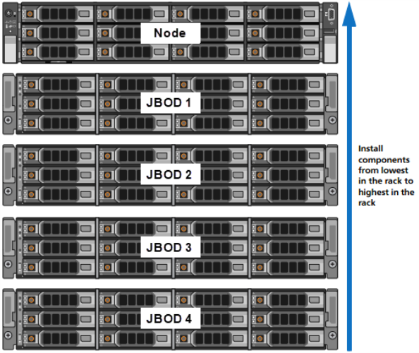
The DXi4800 system is designed to fit in a standard 19 inch (48.3 cm) wide rack. It is important for the chassis installation to locate the hole pattern in the rack rails. You must allow 2U (3.4 inches or 8.7 cm) of vertical space for the DXi4800 Node and an additional 2U for each Expansion module (JBOD) installed in the rack.
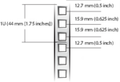
Rack cabinets that meet EIA-310 standards have an alternating pattern of three holes per rack unit with center-to-center hole spacing (beginning at the top hole of a 1U space) of 15.9 mm, 15.9 mm, and 12.7 mm (0.625 inch, 0.625 inch, and 0.5 inch) for the front and back vertical rails. Rack cabinets may have round or square holes. For more information, see DXi4800 Site Planning.
Rail Hole Pattern
WARNING: If the rack is empty at the time of installation, do NOT install the DXi4800 chassis too high in the rack. The weight of the chassis may cause the rack to become “top heavy” and unstable if installed in the top of an empty rack.
To mark the rack, place a mark (or tape) on the rack’s front vertical rails where you want to locate the bottom of the unit you are installing in the rack. The bottom of each 1U space is at the middle of the narrowest metal strip between holes (marked with a horizontal line on some rack cabinets).
Follow the installation procedure for the Gen1 or Gen 2 Expansion Module below:
- Position the left and right rail end pieces labeled FRONT facing inward, and orient each end piece to seat in the holes on the front side of the vertical rack flanges.
- Align each back end piece in the bottom and top holes of the desired U spaces.
- Engage the back end of the rail until it fully seats on the vertical rack flange and the latch clicks into place. Repeat these actions to position and seat the front end piece on the vertical rack flange.
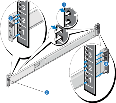
| Item | Description |
|---|---|
| 1 | Latches click into place in rack flange (round or square holes). |
| 2 | Rail front end. |
| 3 | Latch release button. |
| 4 | Rail back end. |
WARNING: The DXi4800 Expansion module (JBOD, including hard drives) weighs 63 pounds (28.6 kg). A minimum of two people are required to lift the chassis. To lift the chassis, use the slots in the packing foam to place your hands under the sides of the chassis.
Caution: Before proceeding, ensure that all hard drive latches are completely closed. Quantum recommends that you do not remove the hard drives from the chassis. If they have been removed for any reason during or after the installation, you must install the hard drives in the same position in which they were removed.
- Align the Expansion module with the rails, and then slide the module into the rack.
-
Tighten the thumbscrews on each side of the Expansion module’s front panel.
Note: To remove the Expansion module, loosen the thumbscrews and slide the Expansion module out of the rack.
-
Install the end caps on either side of the module by inserting the top of the end cap first and then snapping the bottom into place.
Install the end cap with the indicator icons to the left of the module, and install the end cap with the drive numbers to the right of the module.
Note: To remove the Expansion module, remove the screws and slide the module out of the rack.
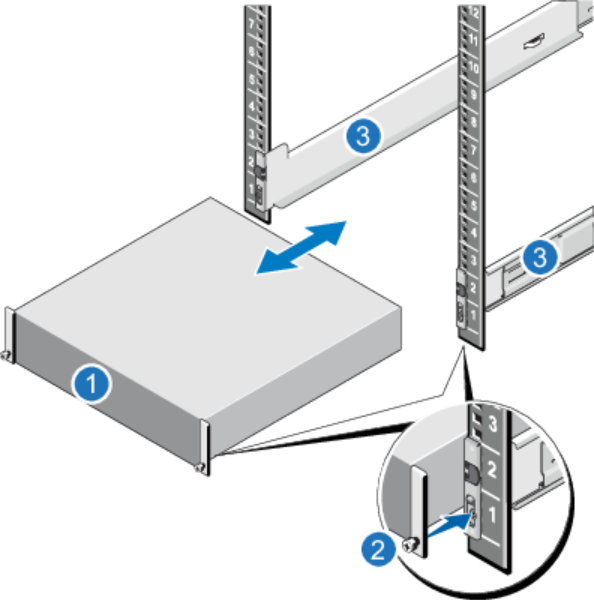
| Item | Description |
|---|---|
| 1 | Front of Expansion Module |
| 2 | Thumbscrew |
| 3 | Rails |
-
Remove both outer rail assemblies from their packaging.

Item Description 1 Left front mount bracket 2 Left front outer rail 3 Left rail slides 4 Set screw, front
5 Set screw, rear 6 Left rear mount bracket -
Orient the outer rail with the LH FRONT embossed on it to your left, the other with the RH FRONT embossed on it to your right, and each emboss toward you, facing inward.
-
Loosen, but do not remove, the 2 set screws on each outer rail with a Philips screwdriver.
-
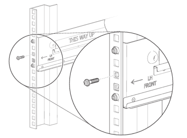
Facing the left side of the rack cabinet, slide the left front mount bracket pins into holes in the front rack post.
-
Bias the left rack mount bracket as far inward as possible, then verify the entirety of the lower rail tab is visible just beyond the inner edge of the front rack mount bracket. This step is crucial to safety and proper storage enclosure operation.
-
Hold the biased mount bracket in that position.
-
Insert a Philips-head M5 x 15 screw into the center hold of the front mount bracket and barely tighten against the front rack using a Philips screwdriver or 8mm nut driver.
-
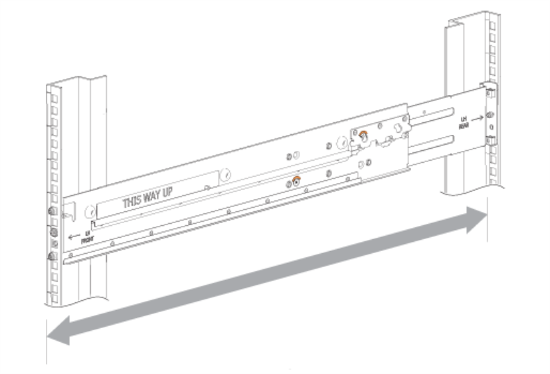
Extend the length of the rail until fully mating the rear mount bracket pins in the mirror location on the rear rack post.
-
Verify that the rails are level at the same height on both rack posts, and that all mount bracket location pins fully seat in indentical locations in the rack posts.
-
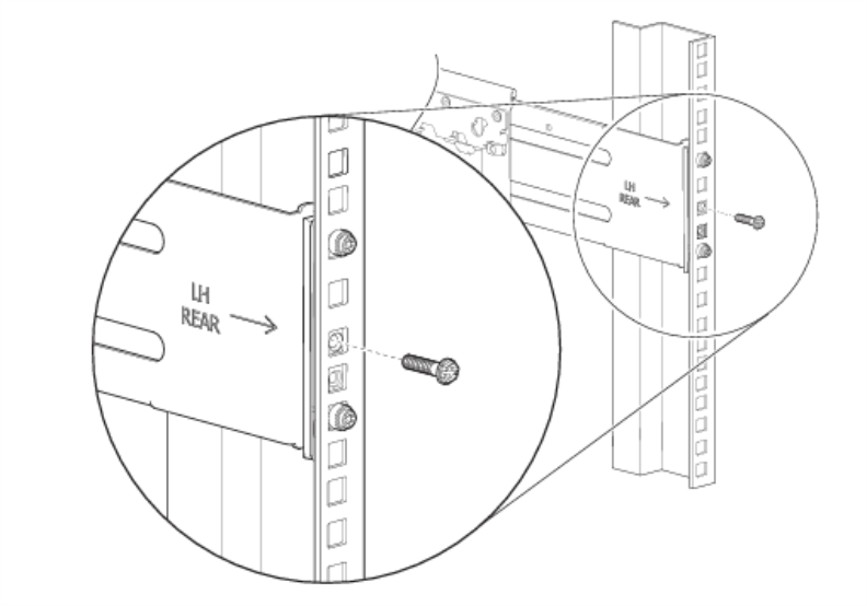
Facing the rear of the cabinet rack, insert a Phillips-head M5 x 15 screw into the center hole of the rear mount bracket.
-
Hand tighten firmly against the rack post using an 8mm nut driver or a Philips screwdriver.
-
Facing the front of the rack cabinet, hand tighten the Phillips-head M5 x 15 screw using an 8mm nut driver or a Philips screwdriver so that the hex head flange is flush with the front rack post.
-
Fix the adjusted length of the left outer rail by hand tightening both rail slide set screws using a Philips screwdriver.
-
Repeat the process for the right outer rail.
Install the DXi4800 Gen2 Expansion Module
WARNING: The DXi4800 Expansion module (JBOD, including hard drives) weighs 71 pounds (32.2 kg). A minimum of two people are required to lift the chassis. To lift the chassis, use the slots in the packing foam to place your hands under the sides of the chassis.
Caution: Before proceeding, ensure that all hard drive latches are completely closed. Quantum recommends that you do not remove the hard drives from the chassis. If they have been removed for any reason during or after the installation, you must install the hard drives in the same position in which they were removed.
-
Confirm that the outer rails are properly and securely installed in the rack cabinet.
-
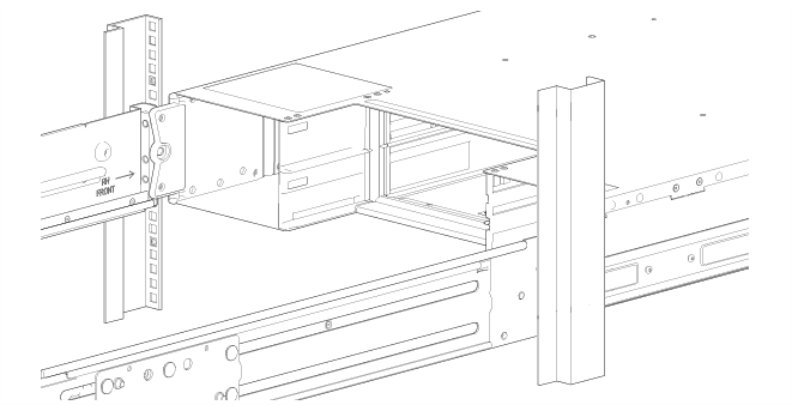
Moving only the 2U chassis, position it so that the attached inner rails align with the outer rails on in the rack.
-
Guide the chassis inward with the leading edge of each inner rail inside the top and bottom lip of the outer rail.
-
Conduct a visual inspection of both sides to verify both inner rails are an equal distance along the outer rail and that the direction is straight, no at an angle.
-
Facing the front of the enclosure, carefully exert even pressure on both sides of the storage enclosure front, inserting the storage enclosure until the rack ear flanges are flush with the front rack posts.
-
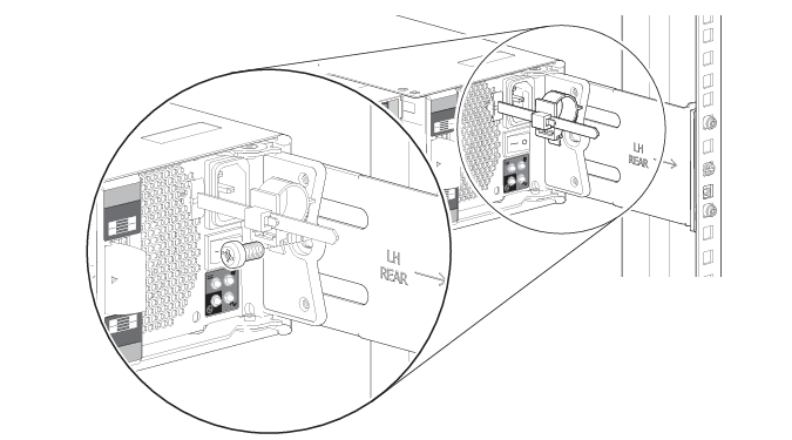
Facing the rear of the enclosure, insert and tighten a Panhead M5 x 8 screw into the tail of each outer rail and through the 2U chassis to secure the rear of the chassis.
-
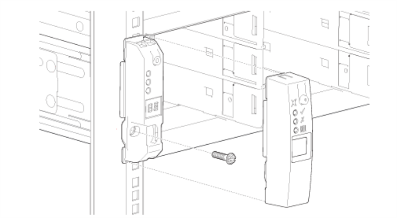
Facing the front of the 2U chassis, insert a Panhead M5 x 8 screw into the operator's (ops) panel with an 8mm nut driver or Philips screwdriver.
-
Hand tighten firmly against front rack post at the center of the rack ear flange.
-
Slide the ops panel cover over the left rack ear flange until flush with the rack post.
-
Repeat the process for the right rack ear flange and cover.
-
Position the left and right rail end pieces labeled FRONT facing inward, and orient each end piece to seat in the holes on the front side of the vertical rack flanges.
Make sure to align the pins correctly with the holes, as inserting them in the wrong holes may bend them. The top of the rail front end should be flush with the desired line on the vertical rack flange.
- Align each back end piece in the bottom and top holes of the desired U spaces.
- Engage the back end of the rail until it fully seats on the vertical rack flange and the latch clicks into place. Repeat these actions to position and seat the front end piece on the vertical rack flange.
Remove the Rails
If you need to remove the rails, use a flat head screwdriver to lift the latch release button on the end piece midpoint and unseat each rail.
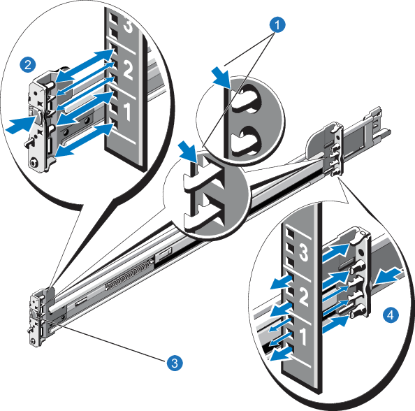
| Item | Description |
|---|---|
| 1 | Latches click into place in rack flange (round or square holes) |
| 2 | Rail front end |
| 3 | Latch release button |
| 4 | Rail back end |
Caution: Before proceeding, ensure that all hard drive latches are completely closed. Quantum recommends that you do not remove the hard drives from the chassis. If they have been removed for any reason during or after the installation, you must install the hard drives in the same position in which they were removed.
- Pull the inner slide rails out of the rack until they lock into place.
- Locate the rear rail standoff on each side of the system and lower them into the rear J-slots on the slide assemblies.
- Rotate the Node downward until all the rail standoffs are seated in the J-slots.
- Press the slide-release lock buttons on both rails and slide the system into the rack. (Make sure the Node is squarely aligned with the rack as you slide it in.)
Note: To remove the Node, locate the lock levers on the sides of the inner rails. Unlock each lever by rotating it up to its release position. Grasp the sides of the system firmly and pull it forward until the rail standoffs are at the front of the J-slots. Lift the system up and away from the rack and place it on a level surface.
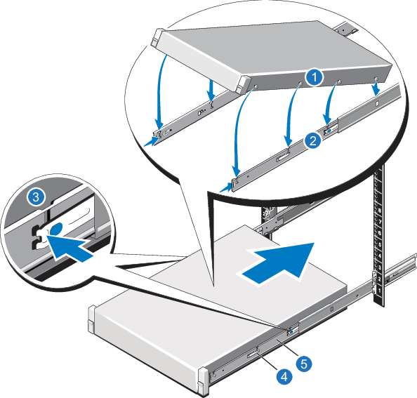
| Item | Description |
|---|---|
| 1 | Rear rail standoffs |
| 2 | Rear rail J-slots |
| 3 | Slide-release lock button |
| 4 | Lock lever |
| 5 | Inner slide rails |
Follow these steps to cable the DXi4800:
-
Connect each Gen1 Expansion module (JBOD) to the DXi4800 Node.
Node JBOD 1 JBOD 2 JBOD 3 JBOD 4 SAS port 1 (left) Primary SAS In port 1 (top) SAS port 2 (right) Secondary SAS In port 1 (bottom) Primary SAS port 2 (top) Primary SAS port 1 (top) Secondary SAS port 2 (bottom) Secondary SAS port 1 (bottom) Primary SAS port 2 (top) Primary SAS port 1 (top) Secondary SAS port 2 (bottom) Secondary SAS port 1 (bottom) Primary SAS port 2 (top) Primary SAS port 1 (top) Secondary SAS port 2 (bottom) Secondary SAS port 1 (bottom) 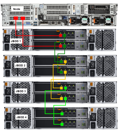
-
If Fibre Channel cards were installed, connect Fibre Channel cables to each Fibre Channel port. If there is a port cover on the port, you must remove it before connecting a cable.
Additional Information
- All Fibre Channel ports are configured for VTL by default. PTT ports can be configured in the Remote Management console once the system is operational.
- Review the SAN Configuration Recommendations below.
Fibre Channel Cabling (VTL/PTT Configurations Only)

Item Description 1 To PTT or VTL (optional) 2 To PTT or VTL (optional) 3 To PTT or VTL (optional) 4 To PTT or VTL (optional) -
Connect each power supply to a primary and secondary AC power source using the provided power cables.
Additional Information
- Quantum recommends connecting each power cord to a separate AC circuit to ensure system availability in case of a power failure. Power supplies should be checked periodically for audible and LED warnings.
- Use the attached straps to secure the power cords to the chassis.
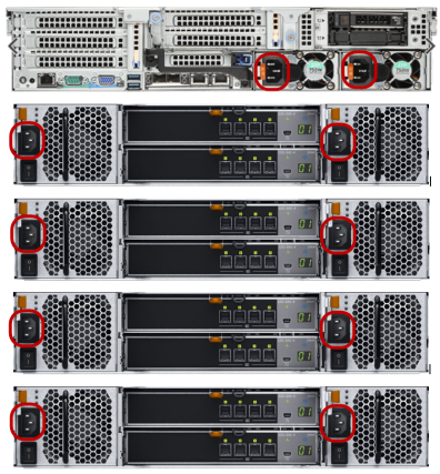
After all cables are attached, move each cable to the left and right, then gently pull straight out to confirm that the cable is locked.
WARNING: If cables are not secure when connected to the modules, the software will not recognize the modules at startup.
Ethernet Cables
Do not connect any Ethernet cables at this time. You will connect them in a later procedure.
-
Connect each Gen2 Expansion module (JBOD) to the DXi4800 Node.
Node JBOD 1 JBOD 2 JBOD 3 JBOD 4 SAS port C1 (left) Top IOM - SAS Port B SAS port C2 (right) Bottom IOM - SAS Port B Top IOM - SAS Port C Top IOM - SAS Port A Bottom IOM - SAS Port C Bottom IOM - SAS Port A Top IOM - SAS Port C Top IOM - SAS Port A Bottom IOM - SAS Port C Bottom IOM - SAS Port A Top IOM - SAS Port C Top IOM - SAS Port A Bottom IOM - SAS Port C Bottom IOM - SAS Port A 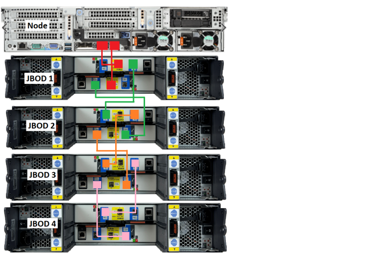
-
If Fibre Channel cards were installed, connect Fibre Channel cables to each Fibre Channel port. If there is a port cover on the port, you must remove it before connecting a cable.
Additional Information
- All Fibre Channel ports are configured for VTL by default. PTT ports can be configured in the Remote Management console once the system is operational.
- Review the SAN Configuration Recommendations below.
Fibre Channel Cabling (VTL/PTT Configurations Only)

Item Description 1 To PTT or VTL (optional) 2 To PTT or VTL (optional) 3 To PTT or VTL (optional) 4 To PTT or VTL (optional) -
Connect each power supply to a primary and secondary AC power source using the provided power cables.
Additional Information
- Quantum recommends connecting each power cord to a separate AC circuit to ensure system availability in case of a power failure. Power supplies should be checked periodically for audible and LED warnings.
- Use the attached straps to secure the power cords to the chassis.
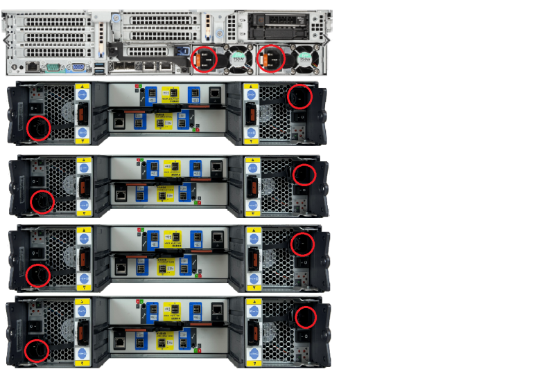
Note: After all cables are attached, move each cable to the left and right, then gently pull straight out to confirm that the cable is locked.
WARNING: If cables are not secure when connected to the modules, the software will not recognize the modules at startup.
Ethernet Cables
Do not connect any Ethernet cables at this time. You will connect them in a later procedure.
5. Perform Initial Configuration
Before the DXi4800 is operational, you must configure the system through the remote management console. You must also configure your backup software.
Configuring the DXi4800 consists of five major steps. See the following subsections for detailed instructions for completing each step:
Note: You will need a notebook computer and an Ethernet cable to complete the initial configuration.
To access the DXi4800 remote management console:
-
Turn on the DXi4800 system components in the following order:
-
Turn on both power switches on the back of each Expansion module. Wait 30 seconds for the Expansion modules to initialize. Verify on the front panel that the modules have power and there were no hard drive failures (Drive status indicator on hard drive blinks amber four times per second).
Gen1 Power Switches

Gen2 Power Switches

-
Press the power button on the front of the Node. Wait for the system to boot before continuing with the procedure. (This can take up to 30 minutes.)
Note: The system may reboot one or more times depending on the components that were installed. If all components are properly installed and cabled, the LEDs on all hard drives in the Node and the Expansion modules will be lit. (The top LED will be solid and the bottom LED will blink.)

-
-
Using an Ethernet cable, connect the Ethernet port on the notebook computer to the installation port (em4) on the back of the DXi4800.

-
Configure the network settings on the computer:
Note: This procedure assumes you are running Windows 7 on the computer. The steps might be different if you are using another operating system.
- Access the Network Connections control panel. To do this, press the Windows key on the keyboard, type view network connections, and press Enter.
-
Right-click the network connection that corresponds to the Ethernet port on the computer (for example, Local Area Connection), and click Properties.
-
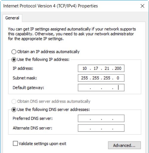
Select Internet Protocol Version 4 (TCP/IPv4) in the list of connections, and then click Properties.
The Internet Protocol Version 4 (TCP/IPv4) Properties window displays.
-
Select Use the following IP address and then enter the following information:
Caution: Before changing the IP address information, write down the original settings. This will be used later to reset the network configuration.
- IP address - 10.17.21.200
- Subnet mask - 255.255.255.0
-
Click OK, and then click Close.
-
Wait at least two minutes for the computer to set the IP addresses on the local computer.
-
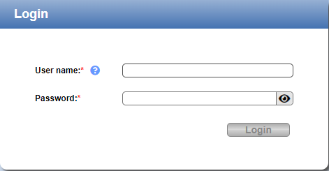
On the computer, open a supported Web browser, type 10.17.21.1 in the Address box, and press Enter.
The Login window displays.
Additional Information
- The DXi GUI is compatible with Chromium-based web browsers. Quantum-tested Chromium-based browsers include Brave, Google Chrome, Microsoft Edge, Opera and Vivaldi. Mozilla Firefox is also compatible with the GUI.
- If the Login window does not display, verify that you entered the correct IP address (10.17.21.1) and that the network settings on the computer are correct. Wait 10 minutes, then try again. If the Login window still does not display, contact Quantum Customer Support.
- If you are using the Firefox browser and find that after you have entered your credentials, the Login button is grayed (inactive), try using Backspace to delete your Password entry, then press Enter, re-enter your Password and click Login.Quantum also recommends disabling the saved login credentials feature when using the Quantum DXi4800 through Firefox. If you encounter further login problems, contact your system administrator.
Continue with the next section to log on to the system and complete the Getting Started wizard.
To complete the DXi4800 Getting Started wizard:
-
Select the login user name and password.
- User name - Type your user name in the field.
- Password - Type password in the field at your first system login.
-
If you log in as a user assigned to the Admin role (local or LDAP) and there were previous unsuccessful DXi4800 logins, a dialog box appears indicating the previous number of unsuccessful login attempts for both the current account and all accounts on the DXi4800.
- Click OK to continue.
-
Click View Admin Log to access the Administrative Activity Log page. See Administrative Activity Log.
Note: Accessing the Administrative Activity Log page will cause the security message banner and service ticket banner (if applicable) to not display.
- Click Reset Counts to reset the unsuccessful login count to zero.
-
Read the information about the wizard, and then click Next to continue.
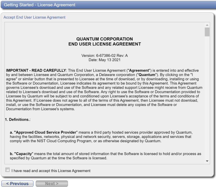
The License Agreement page displays.
-
Select the I have read and accept this License Agreement check box, and then click Next to continue.
Note: If you do not accept the license agreement, the DXi4800 will not function.
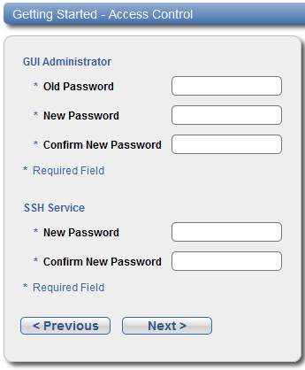
The Access Control page displays.
-
Create a new password for the GUI Administrator user account:
- Enter the Old Password (password).
-
Enter a New Password.
Note: The GUI Administrator password can be up to 32 characters. Alphanumeric characters and special characters are allowed.
- Enter the new password again in Confirm New Password.
-
Create a new password for the Service SSH (ServiceLogin) user account:
-
Enter a New Password.
Additional Information
- The Service SSH password can be up to 20 characters. Alphanumeric characters and special characters are allowed.
- The Access Control page in the Remote Management Console allows you to change the password of the SSH Service account.
- Enter the new password again in Confirm New Password.
-
-
Click Next to continue.
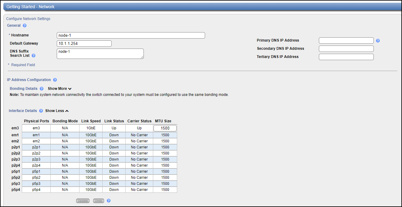
The Network page displays.
IMPORTANT - READ BEFORE CONTINUING
Steps 7-12 below provide an example of configuring network settings on the DXi4800. In this example, the DXi4800 is configured as follows:
- All Ethernet ports are configured as individual devices (Not Bonded).
- A single network interface with one IP address is configured for eth1.
- All traffic types (management, data, and replication) travel over the single network interface.
- All other settings are at default values.
The actual network settings you will enter depend on the configuration of your company’s network and may differ from those below. Work with your network administrator to determine the correct settings for integrating the DXi4800 into your company’s network.
If you set up the DXi4800 using the example below, you can always change the network settings as needed at a later time. For more information, see the “Network” section in the Quantum DXi4800 User’s Guide.
Caution: For effective bonded network use, a properly configured network switch is required. (A network switch is not supplied with the DXi4800.) The DXi4800 bonding settings must match the switch settings. If the switch settings and the DXi4800 settings do not match, your system may become inaccessible through the switch.
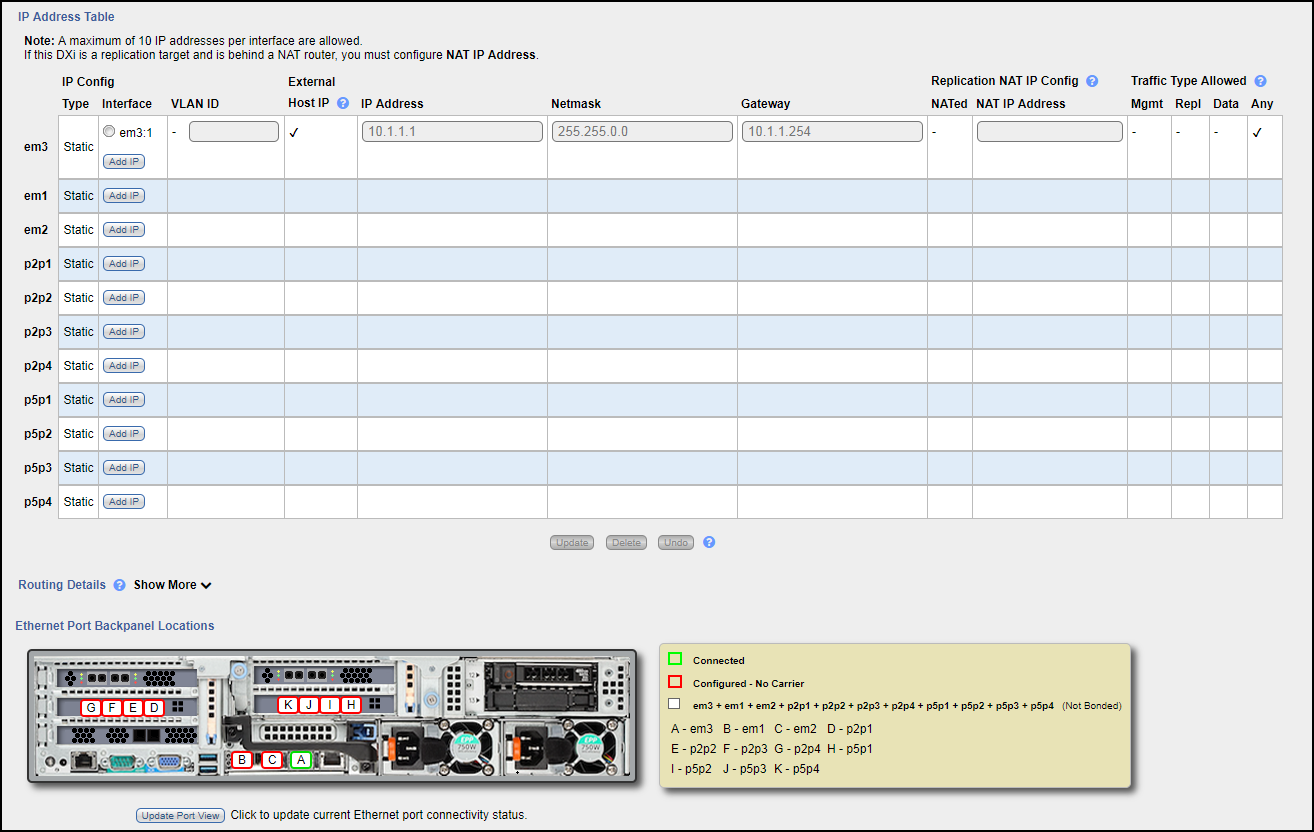
Note: The figure below is for illustrative purpose only. The Network page will reflect the actual number of physical ports in the system.
-
Under General, enter the following network information as provided by your network administrator:
-
Enter the Hostname used to identify the DXi4800 system.
The Hostname cannot be blank and must contain only letters [ A–Z, a–z ], numbers [ 0–9 ], hyphens [ - ], underscores [ _ ], and dots [ . ].
-
(Optional) Enter the Default Gateway IP address.
Specifying a default gateway is optional if all access is local to a particular subnet. For example, if the DXi4800 and all of its clients are on the same subnet, you do not need to specify a default gateway.
Caution: Specifying a default gateway is required to enable connectivity with all subnets other than those that the DXi4800 is directly connected to. For example, if the DXi4800 and its clients are on different subnets, you must specify a default gateway.
-
(Optional) In the DNS Suffix Search List box, enter the local domain to search first when resolving domain names.
The domain suffix is a single domain name. The domain name may contain only letters (A–Z), numbers (0–9), dots (.), and hyphens (-).
-
(Optional) In the Primary, Secondary, and Tertiary DNS IP Address boxes, enter the IP address of up to three DNS servers used to resolve domain names and translate them into IP addresses.
Caution: You must specify a DNS IP address if you plan to use hostname format when configuring an NTP time server, outgoing e-mail server, replication sources and targets, and other information.
-
-
Under IP Address Configuration > Bonding Details, configure each Ethernet port as a separate network device:
- If necessary, click the Show link to show the bonding details table.
- In the Not Bonded row, make sure each Ethernet port is selected (eth1, eth2, and so on).
- If necessary, click Update to save the changes you made to the Bonding Details table.
- Do not make any changes under IP Address Configuration > Interface Details unless directed by your network administrator. (For more information about the VLAN tag and MTU size options, see the “Network” section in the Quantum DXi4800 User's Guide.
-
Under IP Address Configuration > IP Address Table, enter network information for the eth1 device:
Note: Do not make any entries in the VLAN ID, External Host IP, NATed, or NAT IP Address columns unless directed by your network administrator.
- Select the eth1 row in the table. Or, if necessary, click Add IP in the eth1 row to enable entry in the IP Address box.
-
Enter the following network information as provided by your network administrator (all fields are required):
Caution: Make sure you enter the correct IP address information and that you write this information down. If you enter the incorrect IP address information and reboot, you will not be able to access the system.
- IP Address - The IP address of the DXi4800.
- Netmask - The network mask of the DXi4800.
- Gateway - The gateway of the DXi4800. (This is usually not the same as the default gateway.)
- Select the Any check box to allow all traffic types (management, replication, and data) on the interface.
- Click Update to save the changes you made to the IP Address table.
-
Do not make any changes under IP Address Configuration > Routing Details unless directed by your network administrator.
Note: If the DXi needs to communicate with another subnet that is not reachable using the default gateway, a route must be added under the Routing Details section. (For more information about interface routing, see the “Network” section in the Quantum DXi4800 User's Guide.
-
Click Next to continue.
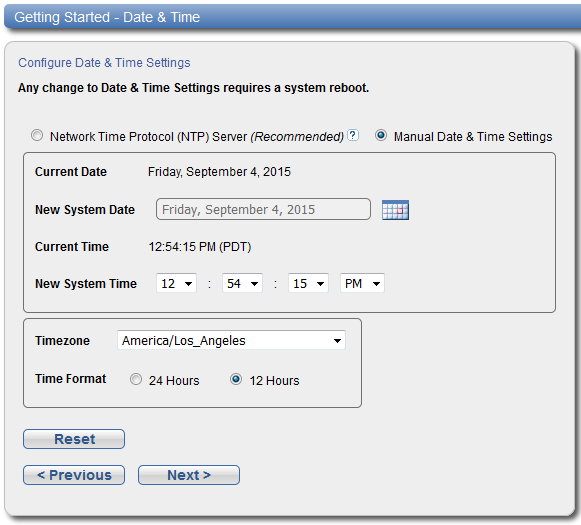
The Date & Time page displays.
-
If necessary, select Manual Date & Time Settings to manually set the system date and time.
Specify the New System Date by clicking Calendar. Specify the New System Time using the drop-down boxes.
Note: You can also choose to synchronize the system time with an NTP time server.
- In the Timezone drop-down box, select the time zone where the DXi4800 is located.
- Next to Time Format, select the format to use when displaying times (24 hours or 12 hours).
-
Click Next to continue.
The Confirm page displays.
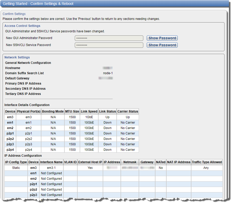
- Review the settings you selected to make sure they are correct. If necessary, click Previous to return to a previous step to make changes
-
After you have confirmed all settings, click Finish.
A message appears stating that completing the setup will restart the system.
- Click Yes to restart the system.
- Disconnect the computer from the DXi4800 service port. Reset the computer network settings back to the default values.
-
Wait for the system to fully restart. This can take up to 30 minutes.
Continue with the next section to connect the Ethernet cables.
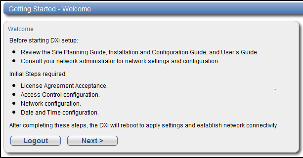
The Welcome page displays.
Note: If a message on the page indicates the DXi is in Limited Mode, wait ten minutes, and then log on again.
Connect the Ethernet cables to the DXi4800 Node as follows:
Depending on configuration, there are three 10 GbE (SFP+) options (Optical, Twinax, CAT6) and 25 GbE (SFP28 optical or DAC copper, for NAS, Application Specific, OST, and replication connectivity) available. Connect the appropriate cable for your system:
| Option | Description |
|---|---|
| Optical |
Insert an SFP+ unit into the 10 or 25 GbE ports and connect up to 18 10 GbE optical or 8 25 GbE SFP28 optical or DAC copper cables. Note: Quantum DXi4800 systems support 10 or 25 GbE optical cable lengths of up to 300 meters with OM3 cables and up to 100 meters with OM2 cables. Quantum recommends using the DXi4800 10 meter LC to LC optical cable type that are shipped with the DXi4800 system. Consult your Optical switch/SFP documentation for additional information on optical cable requirements. |
| Twinax |
Connect up to 18 10 GbE or 8 25 GbE Twinax cables to the 10 GbE ports. Note: The 10 GbE or 8 25 GbE Copper (Twinax) cable options that Quantum provides do not support all switches. Some switch vendors allow only their cables to be used to connect the switches they produce. Please note the supported switches during the purchase-configuration process, and if the Twinax cables supplied by Quantum are not compatible with your switch, please obtain the vendor’s compatible Twinax cables from your switch vendor. Be sure to have these available before the system installation takes place. |
| CAT6 | Connect up to 16 CAT6 Ethernet cables to the 10 GbE ports. |
Note: The Ethernet cables are used for remote management, NAS, Application Specific, OST, and Replication connectivity. Review to determine the number of Ethernet cables to attach. When connecting and disconnecting Ethernet cables or making configuration changes, it is normal for the Admin Alert indicator to display on the remote management console.
Caution: Ethernet and Fibre Channel cables can be damaged when tightened with plastic zip ties. Use hook and loop cable straps instead.
10 or 25 GbE Ethernet Cabling

| Item | Description |
|---|---|
| 1 | To 10 or 25 GbE network (optional). |
| 2 | To 10 or 25 GbE network (optional). |
| 3 | To 10 or 25 GbE network (optional). |
| 4 | To 10 or 25 GbE network (optional). |
| 5 |
To 10 GbE network. |
| 6 | em3 1 GbE port, usable just like 10 or 25 GbE ports. |
Install the protective bezel on the front of the DXi4800 Node and Expansion Module(s). The bezel snaps into place on the front of the Node to prevent the removal of the system from the rack.
- Insert the right side of the bezel into the slots on the right side of the Node.
- Snap the left side of the bezel into place.
Note: To remove the bezel, lift the latch on the left side of the bezel.

Before the customer can begin using the DXi4800 for backups, they must configure the system.
Important Information
Before you begin using the DXi4800 for backups, verify the current DXi software version installed. If the software version is 4.9.1 and below, you MUST upgrade to DXi software version 4.9.1.1 or later to provide support for 16 TB drives in the Node. See Verify Latest DXi Software Version.
Here are next steps the customer can take:
Quantum recommends enabling Email Reports after you install your DXi. When enabled, Email Reports periodically sends system configuration and status information to Quantum, including any software upgrades you have installed using the Software Upgrade Utility. Quantum Support can use this information to provide a better support experience in the future.
To configure Email Reports:
- Make sure a valid outgoing e-mail server is specified on the Configuration > Notifications > Email > Server page. Also make sure to select the Enable automatic emails to Quantum check box on this page.
- (Optional) Specify any additional recipients to receive the reports on the Configuration > Notifications > Email > Email Reports > Recipients page.
- Make sure a weekly Email Reports schedule is configured on the Configuration > Scheduler page. Configure two weekly recurring events: one for Status reports and one for Configuration reports.
Use the Configuration Wizards on the Wizards menu to configure the DXi for backups, and to configure additional features:
To learn more about using the Configuration Wizards, refer to the DXi 4800 User's Guide or access the online help by clicking Help from any page in the wizard.
| Wizard | Description |
|---|---|
|
NAS |
Helps you configure the system as a NAS (Network Attached Storage) appliance. NAS shares can be added using CIFS/SMB or NFS protocols. See NAS Wizard. |
| Application Specific | Helps you add and configure shares as application-specific Oracle RMAN or AccentFS shares. See Application-Specific Shares Wizard. |
|
VTL |
Helps you configure the system to present its storage as one or more VTL (Virtual Tape Library) partitions for use with a backup application. See Application-Specific Shares Wizard. |
|
OST |
Helps you configure the system to present its storage as one or more OST (OpenStorage) storage servers for use with a backup application. See OST Wizard. |
|
Replication |
Helps you configure the system to send replicated data to or receive replicated data from another DXi system. See Replication Wizard. |
| Users |
Helps you configure the system to manage users for Application Specific shares, OST storage servers, PTT Backups, Share Administrators, and Workgroup Users for CIFS/SMB shares. See Users Wizard. Note: The Operator user type has limited access to system resources and must be setup via CLI commands or in the system, on the Configuration > System > Security > Users screens. See Manage Users' Server, Share and Partition Access for instructions. |
| Email Alerts |
Helps you configure the system to automatically send notifications and reports to selected recipients. See Email Alerts Wizard. |
|
Support |
Helps you enable licensed features on the DXi , register your system with DXi , and perform other tasks that will aid Quantum customer support in assisting you. See Support Wizard. |
- To configure your backup application to begin performing backups to the DXi, refer to your backup application documentation.
- To learn more about operating the DXi4800, refer to the DXi 4800 User's Guide or access the online help from the remote management console by clicking Help > Help Contents.
- To enable data replication to another DXi™-Series system, refer to Chapter 6, DXi4800 Replication in the DXi User's Guide.
Note: Backup Application Specific Path to Tape (PTT) is not supported in the DXi4801.
Important Information
Before you begin using the DXi4800 for backups, verify the current DXi software version installed. If the software version is 4.9.1 and below, you MUST upgrade to DXi software version 4.9.1.1 or later to provide support for 16 TB drives in the Node.
Quantum recommends ensuring that the latest version of DXi software is installed. See the Software Upgrades section in your DXi4800 User's Guide for more information.
Appendix
If you encounter problems while installing or configuring the DXi4800, see the table below for troubleshooting steps.
| Problem | Corrective Action |
|---|---|
| The system does not power on. | Make sure all power cords are connected to a grounded electrical outlet and the power switches located on the back of the power supplies are on. |
| You are unable to log on to the remote management console using a laptop connected to the DXi4800. |
Make sure the laptop is connected to Ethernet port 1 on the DXi4800 and that the network settings on the laptop are properly configured. Make sure to wait at least 30 minutes after turning on the system before attempting to log on. Try a different Ethernet cable. |
| The following message displays when you log on to the remote management console: There are service tickets that require attention. | Click OK to display the Service Tickets page, or navigate to the Alerts > Service Tickets page. Click a ticket number to view details about the service ticket. Perform any suggested steps listed in the ticket details. |
| The Home page does not display the expected total Disk Capacity. | Make sure the storage capacity license is installed. |
| The storage capacity license is correctly installed, but the Home page still does not display the expected total Disk Capacity. |
|
Quantum recommends the following to ensure a stable Storage Area Network (SAN) operation with virtual or physical tape drive appliances.
Note: The information provided below is for informational purposes only. Quantum is not responsible for issues related to applying the recommendations described below. Check with your software vendor and SAN administrator to verify these recommendations for your specific production environment.
| SAN Item | Recommendations |
|---|---|
| Disable |
|
| Drivers |
|
| Fibre Channel (FC) |
|
| LUNs |
|
| Ports |
|
| Tools |
|
| Zoning |
|
